- Version
-
v1.0.1+10938074204, 2024-09-19
- Editor
-
Florian Gudat
- Module
-
Mastermodul (C533.2 Compulsory module)
https://modulux.htwk-leipzig.de/modulux/modul/6291 - Module Supervisor
-
Prof. Dr.-Ing. Jean-Alexander Müller
- Lecturer
-
Herr Prof. Dr. rer. nat. Andreas Both
Herr M. Sc. Michael Schmeißer - Institute
-
Leipzig University of Applied Sciences
- Faculty
-
Computer Science and Media
Acronyms
Namespaces
This enumeration lists the prefixes and the associated namespace. It will be used as the standard syntax for RDF prefixes. When a prefix is followed by a colon symbol, the part after the colon can be appended to the namespace URI, thereby creating a new URI.
| acl | |
| al |
dynamic (see Custom Vocabulary) |
| claim |
urn:claim# (see Custom Vocabulary) |
| ex |
example |
| foaf | |
| http | |
| interop | |
| ldp | |
| pim | |
| rdfs | |
| solid | |
| st |
The prefixes and namespaces enumerated above are applicable to diagrams, listings, and inline listings throughout the entirety of the document.
Notation
The diagrams in this document were generated using Asciidoctor Diagram 2.3.1[1] and its bundled PlantUML[2] version.
Unless otherwise specified, all framed diagrams will use the UML 2.5.1[3] standard, constrained by the limitations of PlantUML. As defined in the standard, the following abbreviations will be utilized to identify the type of UML diagram:
| cmp |
component diagram |
| sd |
interaction diagram |
| stm |
state machine diagram |
In addition to the UML abbreviation, the following abbreviations are used to identify non-UML diagrams:
| dm |
data model diagram; The information structure is entirely based on RDF, and will be presented as entity-relationship diagrams in Clive Finkelstein’s IE[4] notation, with some additional elements. The text in the double angle brackets will define the entity type (e.g., Dataset, Thing, …). The path labels indicate potential routes through the graph structure, while the number within the bracket indicates the branch that has been taken. |
| wbs |
work breakdown structure; This diagram is a decompositional diagram[5], intended for use in hierarchical structures, originally designed as a project management tool. In this context, it is used to illustrate any kind of hierarchical structure. |
All diagrams and figures presented in this work were created by the author. Any discrepancies have been highlighted in the corresponding figures.
The Solid Project is an RDF-based ecosystem that aims to achieve a decentralized web for individuals, social entities, or software. The technology is still in development and not yet fully evolved. This work proposes an experimental vendor-agnostic approach of extending Solid via a server-side application layer proxy, with the objective of increasing the traceability and access control of requested resources. It also considers the impact of this approach on the system design and performance efficiency.
This document is divided into five sections: the Introduction, Theoretical Framework, Design and Implementation, Analysis, and Reflection. The Introduction will provide a more detailed examination of the research context and the terminology utilized in this document. Fundamental concepts, such as data sovereignty and recommended quality aspects, will be summarized in the Theoretical Framework. The Design and Implementation section will explain the system design concept and the technological choices made. The Analysis section will define the experimental conditions and validate them with the quality criteria described in the Theoretical Framework. The Reflection section will discuss the considerations from the Introduction, describe future work, and conclude the overall research.
Part I: Introduction
The introduction will set out the scope of the research and define the terminology used in this context. The research chapter will begin with a motivating problem and objectives that define the interest in this research. This chapter will also define the design of this research and the concept, including the requirements. The terminology chapter will explain general Solid terms, the understanding of access monitoring, the system definitions, and the proxy design pattern.
1. Research
The topic of decentralized data processing represents a significant and complex area of inquiry within the field of computer science. One of the most significant developments in this field was the advent of the Internet. The server-client model, which separates processing into two parties, has enabled a wide range of consumers to benefit from this concept. In this regard, the use of web applications continued to grow. One of the limitations of this approach is that the data processing and storage are often shifted to the server, which increases the problem of vendor lock-in for one’s own data. In order to overcome this issue, Solid Project was introduced as a vendor-agnostic approach for identity management, data storage, and access granting. It is an RDF-based ecosystem that aims to achieve a decentralized web for individuals, social entities, or software.
The processing of data stored in the private space must be decentralized due to the decentralized nature of Solid. Given the involvement of multiple parties, resources maintained by the Solid Provider are frequently utilized. While access granting for these resources is a significant topic in the Solid Community, the actual access is not part of the scope of Solid, resulting in a lack of transparency and access control.
This thesis aims to develop and analyze a Solid-based application that aligns with the Solid ecosystem without enforcing it. The application will enhance data privacy concerns, specifically in terms of data traceability and access control. The goal is to increase visibility and track requested resources from parties within and beyond the ecosystem through access logs and their representation. These requests should be processed and logged to achieve better control over the exposed data, by monitoring them. All of these achievements should be established in a clear context and communicated through data APIs to ensure safety for new features and potential changes in Solid Providers.
1.1. Problem Definition
The backbone of the Solid project is the Solid Protocol. The protocol specifies how agents store their data securely in decentralized data storages, also known as Pods. These storage systems can be compared to secure, personal web servers for data, such as Dropbox, ownCloud, Nextcloud, or similar software. However, they differ in that they do not have a standardized and unified public API. This interface utilizes WebIDs to identify the agents within the system. As the storage owner has control over which agents can access it, they can choose to restrict access to only WebIDs, completely restrict access, or make it publicly accessible.
The Solid Community Group has been developing this technological approach since 2018. The ecosystem is currently in its early stages of development, and some specifications are still in draft form. Consequently, it may lack some features that are recommended in productive environments. This leads to the following issues:
| ISSUE-1 |
The Solid Protocol only specifies the ability to grant or deny access. It does not track the actual request for a resource. |
| ISSUE-2 |
Solid is based on RDF and therefore favors interconnected data, what increased the demand for monitoring the stored data. |
| ISSUE-3 |
There may be changes to existing specifications as they need to be improved or are still in the draft stage. |
| ISSUE-4 |
The Solid ecosystem will be expanded with newly introduced specifications or APIs. |
| ISSUE-5 |
New Solid Providers are being introduced because of their increasing popularity. |
The first and second issues describe the need for traceability to control access to one’s own data. A general problem with updates is addressed by the third through fifth issues. However, all of these concerns will affect the objectives of this research.
1.2. Objectives and Research Interest
The research has two primary objectives that align with the listed problems. The first goal is to achieve transparency regarding which data has been accessed and by whom. This would significantly increase control over one’s own data. The second objective is to find a solution that can handle the fast-moving Solid ecosystem.
The objectives described leads to the following key research question this paper aims to address:
Is there a Solid-based system design that enables increased transparency and access control for requested personal data? Can the system use the network interface in a vendor-agnostic way without a significant decrease in performance?
As answering this question in one go is difficult, it will be divided into multiple sub-questions:
| QUEST-1 |
Can a Solid-based system meet both functional and non-functional requirements without compromising system design? |
| QUEST-2 |
To what extent does the process contribute to the increase in network requests and load? |
| QUEST-3 |
Which system and test parameters influence the executed test cases? How does the influence of the parameters manifest itself? |
The listed questions cannot definitively determine whether the proposed approach is suitable for use in productive environments. However, they can reveal the vulnerable aspects of this concept to determine whether this approach should be pursued in principle.
1.3. Research Design
The research will employ two different research methodologies, namely qualitative and quantitative, to address the research objectives and research interests. Regarding the qualitative analysis, it is intended to explain how the proposed approach will affect the system design as required by QUEST-1. A quantitative analysis will quantify the expected increase in the network load required in QUEST-2 and QUEST-3.
The identified analyses will be conducted using data and insights collected from an experimental prototype.
The prototype must satisfy the specified requirements, which are derived from the problem definition.
The data set is shown in Table 1.
It contains the timeStamp of the sample and the elapsed time until the test concluded.
As a sequence of network operations is tested, a label for the individual action must be set.
In addition, the responseCode of the HTTP request will indicate whether the operation was successful or erroneous.
The URL is necessary in case further insights into the individual HTTP request are required.
In order to have comparable values, each sample will be taken with and without the considered approach.
Item |
Format |
Example |
|---|---|---|
timeStamp |
number |
1716570602084 |
elapsed |
number |
230 |
label |
string |
Created 0 |
responseCode |
number |
201 |
URL |
string |
http://proxy.localhost:4000/client100/run1716570595598_thread1_loop1_resource0 |
It should be noted that the general proxy functions of delegating and forwarding requests have been excluded from this view. There are various implementations of proxies that must not be considered in this research. However, the DPC proxy module, which runs before and after the client response and request, has been included.
1.4. Concept and Requirements
This section will address the general conceptual idea and subsequent refinements to the idea. Based on the aforementioned idea, the requirements for the prototype will be established in order to achieve the desired outcomes.
1.4.1. Concept
The concept is inspired by existing software solutions in the field of e-governance, such as X-Road from Estonia and XDatenschutzcockpit, which is currently being developed in Germany for access control of citizen data. Both systems have an embedded logging system that monitors access data. Since they are tied to the specific context in which they are used, the idea of a Data Privacy Cockpit (DPC) will be ported to the Solid ecosystem.
When applying the concept to the Solid context, two fundamental software components can be identified to solve the problems under the given premises:
| DPC Middleware |
A server-side proxy module at the application level monitors data traffic and creates logs if necessary. |
| DPC Client |
The traffic data from the reverse proxy is displayed and managed by the client. |
The concept idea’s data capturing unit, the DPC Middleware, will be implemented as a proxy to meet the requirements of vendor-agnostic software that is secure from updates, as criticized in ISSUE-3, ISSUE-4, and ISSUE-5. However, this requires the application to be a Solid application, as it communicates over HTTP APIs with the actual Solid Provider. Since every request passes through the reverse proxy, there is a high risk of resulting in an inefficient software solution.
Upon reflection on the prototype, two central issues of the concept emerge instantly. The first is the manner in which the data is captured by the DPC Middleware. The second is the means by which the DPC Client is aware of the owner or potential accessor of the data captured.
Data Capturing Strategies
In traditional approaches to data capturing, such as the logging or monitoring of access to resources on a web server, data is typically raised in a task that is executed in the background. To illustrate, in the context of Node.js[6], this may be accomplished through the use of libraries such as morgan[7] or winston[8], which can be mounted as middlewares in a web server. In the context of the proposed application, it is necessary to distinguish between requests based on their storage resource, for instance, through the use of a registry. This presents an opportunity for an agent to opt in for monitoring. This leads to two methods that are applicable in the context of how access logs can be captured.
Both options represent viable strategies for consideration. However, the permanent strategy is more restrictive and may not be optimal in this context. In contrast, the opt-in strategy requires an agent to actively initiate access logging, which aligns with the concept of consent, a significant strength of the Solid Ecosystem.
Ownership Verification
In decentralized systems, it appears that a resource cannot be directly associated with an owner. This is also the case in Solid-based systems. Despite the necessity for the system to know the ownership of the individual resource, it may not be exposed to the public. One solution to this problem is to write a randomized verification token in the space associated with the owner. This approach will be used within the prototype developed. This ensures that the requester has a minimum level of privileges to the resource space. It works in a manner analogous to other services, such as Google’s Search Console[9]. A similar challenge is faced by these services, namely that the DNS server is only aware of the domain name and IP address relationship, but lacks the information necessary to determine the ownership of the domain name.
1.4.2. Requirements
The tension between vendor-agnostic software and efficiency is a key consideration for the solution’s requirements, particularly in non-functional requirements. However, the functional requirements are straightforward.
Functional Requirements
The following list outlines the minimum functions that the prototype must have in order to answer the questions.
Non-Functional Requirements
In comparison to the functional requirements, establishing the following non-functional requirements is more challenging. However, they are even more important as they verify the general conceptual idea.
The proposed solution is based on both functional and non-functional aspects. The objective is to develop a prototype that meets the client’s requirement for traceability of accessed resources while operating accurately within a Solid ecosystem.
The conceptual idea is considered successful if the requirements could be satisfied adequately. The adequacy will be evaluated with the prototype, as described in the Research Design.
2. Terminology
2.1. Access Control and Traceability
Access Control represents one of the primary use cases of the Solid Protocol, which utilizes Authentication and Authorization. It primarily concerns the granting and revocation of access privileges, with the objective of providing a systematic response to the question of who is permitted to perform which actions at which locations and times (Fischer & Hofer, 2011).
Traceability, is defined in two distinct ways. On the one hand, it can be understood as a step-by-step examination of a program during troubleshooting. Alternatively, as in the case examined in this work, it refers to the tracing of a route of data in communication. However, it should be noted that there is no uniform specification that allows for this definition to be universally applied (ibid.).
Extending access control and traceability means enabling an option that allows the tracing of a route of data. This allows users to have greater control of the exposed data and access privileges given. This should, in general, enhance access control, which might become obscured in a growing decentralized and highly connected ecosystem.
2.2. System
Systems are defined in several ways, as Fischer & Hofer (2011) have observed. In general, a system is a combination of interrelated elements that fulfill a common purpose. In computer science, a system is an arrangement of interacting objects that is limited in scope. According to the more concrete definition, a system is the sum of all hardware and software components of a data processing system from the point of view of their interaction.
2.2.1. Network Interfaces
In the context of a data-driven web-based system, the interaction of the system is further concretized. The system must interact via data APIs over the network. This is sometimes referred to as Resource-Oriented Architecture (ROA), as defined by Richardson & Ruby (2007). ROAs are designed to facilitate the manipulation of resources through four operations: creation, reading, updating, and deletion (CRUD). In this architecture, the CRUD operations are mapped to the following HTTP request methods:
| CREATE |
The |
| READ |
The |
| UPDATE |
The |
| DELETE |
The |
2.2.2. Resource CRUD Lifecycle
When applying the CRUD network interfaces to a single resource lifecycle, every achievable state (created, read, updated, and deleted) is reached by an ingoing CRUD transition. The starting state, however, must be the created state in order to have an initial resource to work with. Until its deletion, the same resource cannot be created again. New resources, however, can be created at any time. All other states (read, updated, and deleted) are accessible from the created state as well as the updated and read state, including self-transitions. When the deleted state is the current state of the resource, the only possible transition is the recreation of the resource. This behavior is displayed in Figure 1.

It is recommended that a sequence of CRUD requests, utilising states and transitions as previously described, be executed in a sequential order. Certain sequences may allow parallel execution, however, it can lead to errors due to the occurrence of illegal transitions. An illustrative example of transitions that are executable in parallel is a sequence of only read transitions on an existing resource. These transitions should be executable in parallel without any issues, as a situation where a resource is attempted to be read before its creation cannot occur.
Another scenario to be considered is the utilisation of resources with a deeper hierarchical depth, which are typically designated with a backslash in the URL. In such instances, the resource container can be treated as ordinary resources, with a CRUD network interface and the corresponding lifecycle. However, it is not possible for a resource to exist independently of a parent container resource in the created, updated, or read state.
It is important to note that each state of the state machine can be a final state.
The transitions in this context are translated with different frequencies.
For instance, read transitions appear more often than others.
This segmentation is represented as a probability in this work.
2.3. Proxy
Gamma (2011) defines a proxy as a structural design pattern in software development that serves as a placeholder for another object to access or control. This improves efficiency and reduces complexity. In this case, the accessed object is the Solid Provider.
Proxies can be classified into a variety of groups. In this study, we focus on web proxies, as the communication between the proxy and the Solid Provider will use HTTP APIs. The categorization of proxies is based on the position within the client-server model, as well as the OSI layer in which it is operational.
2.3.1. Server-Side Proxy
The internet operates on the Client-Server model, where a client requests a resource from the server, which responds accordingly. Introducing a proxy to this model involves adding another server. This proxy server accepts requests and delegates them to the actual server. The response is then forwarded to the requesting party. However, this offers the opportunity for a proxy to isolate either the client or the server from the network. When referring to a server-side proxy, isolation of the server is described, as shown in Figure 2 (Luotonen & Altis, 1994).

2.3.2. Application Layer Proxy
In addition to its position within the network, the Proxy can also have a position in the OSI model. The model describes how data will be transported in seven layers, each with different functions. Every layer can only communicate with its closest layer, starting with the physical layer that transmits a raw bitstream over a physical medium, up to the seventh layer, the application layer. This is the human interaction layer, through which applications can access network services. An Application Layer Proxy operates within this layer.
For the sake of simplicity, the term "proxy" will be used in the following text. Despite the abbreviated term, all properties of a server-side application layer proxy will be fulfilled.
Part II: Theoretical Framework
The theoretical framework is intended to serve as a foundation for the concepts and technologies that are the subject of the research. One of the central aspects is the Solid Ecosystem, which will be explained in chapter four. The ecosystem comprises several elements, and in this chapter, in particular, the Solid Protocol, Solid Provider, Solid Application Interoperability, and its limitations will be presented. The second chapter will refer to the concept of Data Sovereignty within the ecosystem. In this context, the concept of data trustees, the strategies for data capturing and the verification of ownership will be explained. Finally, the Quality Model will be demonstrated, which is necessary to perform an analysis of the system design and performance efficiency.
3. Solid Ecosystem
The Solid Project is an RDF-based ecosystem that aims to achieve a decentralized web for individuals, social entities, or software. The ecosystem comprises a number of specifications and associated technologies, which are primarily listed in the Solid Technical Reports[11]. The most fundamental specification is the Solid Protocol, also known as the core specification. In addition to the core specification, the following sections will explain the role of Solid Providers in enabling the protocol and the Solid Application Interoperability specification, which extends the protocol.
3.1. Solid Protocol
According to the Mozilla Developer Network (2023), a protocol is a set of rules for exchanging data between computers. Fischer & Hofer (2011, p. 706) provide additional clarification on this topic. The protocol includes setup, termination, collision prevention or correction, content integrity, and the actual actions within the same layer.
The Solid Protocol is a type of protocol that encapsulates a modified set of new and existing specifications to fit into the ecosystem. The Protocol Specification includes additions and adoptions, or references to the original ones (Sarven et al., 2022). The specifications included here are only representative of a subset of the definitions relevant to this research, primarily focusing on special http headers, resources, representation, identity, authentication and authorization.
3.1.1. HTTP Headers
The Solid Protocol employs a specific model of the relationships between resources on the Web and the types of these relationships. These are exposed as HTTP headers, linking to the related resource, as defined by Nottingham (2017).
HTTP Link headers are conventional HTTP headers, with the header field Link and a value separated by a colon.
Within the header value, the uri-reference points to the related resource, while the attribute value pair defines the relation.
This is demonstrated in Listing 1.
Link: <uri-reference>; attribute="value"In the event that multiple header values are to be applied, the values may be separated by a comma.
3.1.2. Resources
The Solid Protocol employs a variety of resource definitions, which are constructed upon one another in a hierarchical manner. These definitions either extend or restrict the previous definition, thereby forming a structured system.
The resources listed below are the most common resources in Solid and in the web in general:
| resource |
The target of an HTTP request, identified by a URI (Fielding & Reschke, 2014). |
| container resource |
A collection of resources and resource containers, organized in a hierarchical structure (Sarven et al., 2022). |
| root container |
The top-level resource within a resource container hierarchy (Sarven et al., 2022). |
Storages are spaces of URIs that affords agents controlled access to resources. The storage resource, however, is the root container for all of its contained resources and is owned by an agent (Sarven et al., 2022).
Storage resources are defined by a specific HTTP Link header that is used to mark a given container resource as a storage resource.
This is achieved by including the rel attribute with the value type, along with a URI reference that matches pim:Storage.
The owner of this storage can be made available optionally by including the rel attribute with the value solid:owner.
This is demonstrated in Listing 2, where additional headers and the response have been omitted in the listening (ibid.).
HEAD http://proxy.localhost:4000/client/

HTTP/1.1 200 OK
[...]
link: <http://www.w3.org/ns/pim/space#Storage>; rel="type", <http://www.w3.org/ns/ldp#Container>; rel="type", <http://www.w3.org/ns/ldp#BasicContainer>; rel="type", <http://www.w3.org/ns/ldp#Resource>; rel="type", <http://proxy.localhost:4000/client/.meta>; rel="describedby", <http://proxy.localhost:4000/client/.acl>; rel="acl", <http://proxy.localhost:4000/client/.well-known/solid>; rel="http://www.w3.org/ns/solid/terms#storageDescription", <http://proxy.localhost:4000/client/profile/card#me>; rel="http://www.w3.org/ns/solid/terms#owner"
[...]
As the storage resource is a top-level resource in the container resource hierarchy, all containing resources belong to a storage resource. The containing storage resource is not directly accessible via an HTTP header or any other means. However, the hierarchy can be traversed until the highest level is reached in order to identify the containing storage resource (ibid.).
Description resources represent a distinct category of auxiliary resources.
These resources provide a description of a subject resource, which is referenced by a HTTP Link header.
The rel attribute is used with the value describedby to indicate this relationship.
This is also illustrated in Listing 2 (ibid.).
3.1.3. Representation
The representation of resources is primarily in the form of RDF documents. Bergwinkl et al. (2019) introduced the Dataset specification, which represents the contents of these documents as ECMAScript objects. The Inrupt JavaScript Client Libraries[12] refined this further and introduced the terms SolidDataset and Thing. In order to facilitate the interpretation of the RDF documents, the following definitions will be used, based on the definitions mentioned:
| Thing |
A Thing is a data entity that contains a set of data or properties about the Thing. |
| Dataset |
A dataset is defined as a set of Things, represented as a RDF resource. |
3.1.4. Identity
In a decentralized platform, it is essential to have identifiable. Solid accomplishes this with WebIDs and the WebID Profile, which is associated with it (Sambra et al., 2014).
| WebID |
A WebID is a special resource of RDF type foaf:PersonalProfileDocument, which denote an agent. When a fragment identifier is contained by the URI, the WebID Profile is denoted (ibid.). |
| WebID Profiles |
A WebID Profile is a Thing that serve to uniquely describe an agent, as denoted by the WebID (ibid.). |
3.1.5. Authentication
The authentication process in Solid is based on OAuth 2.0[13] and OpenID Connect Core 1.0[14], with certain enhancements. In order for the resource servers and authorization servers to function, they must have a trust relationship with the identity providers. Furthermore, ephemeral clients are intended to be the primary use case (Coburn et al., 2022).
The authentication is mainly expected to be authorized via the Authorization Code Flow[15]. However, as it is built on top of OIDC, the Client Credentials Flow[16] is a viable option in the majority of implementations, such as CSS[17].
In both cases, an access token will be returned to the authenticating client. Which usually is a Bearer Token in OIDC Sessions. Solid-OIDC however, depends on DPoP tokens. DPoP tokens ensure that third-party web applications can not use the token, as the are protected by a a public and private key pair (Coburn et al., 2022; Fett et al., 2023).
3.1.6. Authorization
Authorization is a fundamental aspect of Solid. Each WebID-owned resource must be authorized, with either or both WAC and ACP publishing mechanisms as specified. This even applies to resources that are publicly accessible and that permit unauthenticated requests. Both mechanisms utilize ACL to grant access to a resource, for a selected agent with defined access privileges. The possible privileges for a resource are read, append, and write access, as well as control access, which is used to manage the access privileges (Sarven et al., 2022; Capadisli, 2022).
3.2. Solid Provider
A Solid Provider is a web server that uses the Solid Protocol and provides the specified APIs and functions as a service. These services can be hosted on a private server or used from public hosting providers. The most common self-hosted implementations are Community Solid Server and Node Solid Server, among others[18]. Both are available on different public hosting providers, in addition to Inrupt PodSpaces[19], which is only accessible as cloud software.
3.3. Solid Application Interoperability
The Solid Specification outlines the overall framework of the system-wide data model.
Additionally, the Solid Application Interoperability Specification[20], an extension to the Solid ecosystem, addresses application-independent design and a uniform mechanism for data discovery.
It should be noted that the Specification has not yet been fully matured or implemented by any Solid Provider.
However, it can be used in part without a full implementation of the Solid extension.
The Editor’s Draft of November 7th, 2023 introduces a mechanism for discovering registered data without requiring knowledge of the physical structure of the file system or HTTP endpoints.
An application only needs to be aware of the profile document and follow the suggested references in the specification.
Figure 3 illustrates these entities and relations.
DataType and DataElement represent a selectable data type and element, respectively.

The entities and relations in Figure 3 represent a partially implemented data registry component of the Solid Application Interoperability specification by Bingham et al. (2023).
As described in the specification, an agent must declare an interop:Agent in the personal profile document to participate in the Solid Application Interoperability Specification.
From there, one can follow the specified path, starting with the registry set, which is referred from the declared agent.
The registry set contains an interop:DataRegistry, which refers to an interop:DataRegistraion.
As the interop:DataRegistraion resource is a resource container (ldp:Container), all contained resources will apply the interop:DataRegistraion attributes.
These attributes are defined in the registered ShapeTree, which is referred to from the interop:DataRegistraion.
The registered ShapeTree defines the shape of the contained resources, by referring to the Shape.
The Shape will point to a Shape Expression once more.
The Shape Expression defines the data types of the predicates utilized in the vocabulary.
3.4. Limits of Solid
One challenge in monitoring storage resources is that the ownership of a resource is not necessarily linked to the requested resource within the storage resource. As previously mentioned in the storage resource section, the path of a URI can be reduced, path segment by path segment, to identify the containing storage. However, the storage is owned by at least one owner due to the specification. This piece of information is not mandatory, which limits the reliability of identification to the storage resource (Sarven et al., 2022).
4. Data Sovereignty
4.1. Data Trustee
In the absence of an owner for the monitored resources, a concept is required to capture data and verify ownership at a later stage. One such concept is that of data trustees, which collect data on behalf of a natural or legal person. In the context of this work, the data trustee is an agent who captures data from the owner of the storage, who is another agent. The data trustee is an independent entity of trust that acts as a mediator between the data provider and the data user, ensuring the secure and legally compliant transfer of data. The concept can be distinguished by the type of data storage, which is either centralized or decentralized, and the type of data use, which is obligatory or optional (Specht-Riemenschneider & Kerber, 2022).
4.2. Data Storage Structure
In general, data storage structures can be divided into two categories when sharing a set of data with other agents that have been granted access to the data in question. The first category is container-based, which involves storing the shared data in a single storage resource and dividing it into container resources. The second category is storage-based, which involves storing the shared data in multiple storage resources, all of which are owned by the same agent.
4.2.1. Container-Based Storage
In a container-based arrangement, all data pertaining to multiple agents is stored in a single storage resource.
A mechanism must be in place or established to enable the agent with the requisite privileges to access the data.
With WAC, two main options exist for defining an Access Object.
In this context, the acl:accessTo option denotes the resource to which access is being granted, whereas the acl:default option denotes the container resource whose authorization can be applied to a resource lower in the collection hierarchy.
Consequently, the location and structure of the storage resource are publicly visible, thereby increasing the risk of information disclosure vulnerabilities.
The process of creating a new container resource however, is well part of the Solid Protocol and thereby the usage is unified.
The process of creating a new container resource, however, is a fundamental aspect of the Solid Protocol, thereby ensuring unified usage.
An illustrative example can be found in Listing 3 (Capadisli, 2022).
POST http://proxy.localhost:4000/client/
Content-Type: text/turtle
Link: <http://www.w3.org/ns/ldp#BasicContainer>; rel="type"
Slug: new-container
The implementation of custom mechanisms to expose data to associated agents may eliminate information disclosure vulnerabilities. However, when bypassing the authorization mechanism provided by Solid, the risk of inadvertently exposing data to an agent that does not have the appropriate permissions increases.
4.2.2. Storage-Based Storage
A storage-based approach to data storage for agents is a convenient method, as it encapsulates the data for an agent in a data space of their own.
This approach ensures that no unnecessary information is shown to the public and that the data is stored in a secure context.
As this is the purpose of a storage container, there is no individual mechanism required to ensure that the data is accidentally exposed to an agent that does not have any privileges to that data.
The acl:accessTo and acl:default mechanisms, which have been applicable in a Container-Based Storage context, can also be applied here.
However, there is a significant disadvantage to this approach over the Container-Based Storage approach.
Namely, there is no unified API in the specification.
While the creation of container resources is defined in the Solid Protocol, the creation of storage resources differs for each implementation. CSS for instance, requests a process in multiple steps, with the final step shown in Listing 4[21].
5e647928-b7f0-4357-9927-f54d66a04790.POST http://proxy.localhost:4000/.account/account/5e647928-b7f0-4357-9927-f54d66a04790/pod/
Authorization: CSS-Account-Token a3395e7c-7d3f-40a1-9dff-7fa25b48c1a9
Content-Type: application/json
{
"name": "new-pod"
}In contrast, Inrupt’s ESS, as an alternative Solid Provider, only requires a simple authorized POST request as shown in Listing 5[22].
POST https://provision.inrupt.com/5. Quality Model
The quality model is a valuable instrument for assessing the quality of a software system. The model can be applied to a variety of aspects, depending on the specific quality criteria that are to be observed. In this section, the System Design Quality and the Performance Efficiency are the aspects that are to be characterized.
5.1. System Design Quality
The determination of the quality of systems and software is a complex process that is challenging to verify. The specific approach taken may depend on the problem to be solved. Martin (2018) distinguishes between the micro architecture view, which considers low-level details, and the macro architecture view, which addresses quality concerns at an abstract level. These concerns can be divided into two categories: Component Cohesion and Component Coupling These categories can be used to determine the quality of a system design, in therms of inner and outer connections.
5.1.1. Component Cohesion
The component cohesion represent general approaches to system design, as defined by Martin (2018). It is used to specifiy components that are ment to be gouped in one package or service. In order to accive that three principles are needed to be satisfied by the system, the Reuse/Release Equivalence Principle, the Common Closure Principle, and the Common Reuse Principle.
The principles outlined here are intended for object-oriented programming, but they are also generic concepts that can be applied to any top-level view of a system, as will be in this context. Therefore, each subsystem of the proposed system will be treated as a package in the object-oriented paradigm.
5.1.2. Component Coupling
The external relationships of a component, namely the connections between one component and another, are referred to as coupling. Four principles are relevant to this matter: the Acyclic Dependencies Principle, Top-Down Design, Stable Dependencies Principle, and Stable Abstractions Principle (Martin, 2018).
These principles are to be taken into consideration when software components are aligned to each other on a top-level view. In addition to the Component Cohesion Principles, they also represent a part of the spectrum of a macroarchitectural view.
5.2. Performance Efficiency
ISO/IEC 25010 is a quality model for the evaluation of system quality. The quality model defines which characteristics are to be considered when a system is developed. It considers various aspects of a software system. In this case, the characteristics of performance efficiency are the central aspect that is observed. It represents the extent to which a system performs its functions, considering the time and throughput necessary, its efficient use of resources, and the capacity used under specified conditions, as listed below:
| Time behavior |
A system’s responsiveness and throughput are measures of its ability to perform the functions it is designed to perform. |
| Resource utilization |
The quantity and type of resources utilized by a system to fulfill its operational requirements. |
| Capacity |
The maximum limits of storage usage correspond to the system parameters. |
The time behavior is of particular importance in this quality model. As the software is a web-based system that individuals are operating with, it is crucial to consider usability. Nielsen (1993) identifies three main time limits (in seconds), which are determined by human perceptual abilities, that should be kept in mind when evaluating the performance of a system.
| 0.1s |
The point at which the user perceives the system to respond instantaneously. |
| 1s |
The maximum limit may result in a delay in the user’s cognitive process, even if the user is aware of the delay. |
| 10s |
The temporal constraint on the user’s ability to maintain their focus on the process. |
In the event that the system is unable to provide a response time that is close to instantaneously, it is necessary to employ visual progression, for example, in the form of a percent-done indicator.
In terms of throughput—one of the key time-behavior aspects—IBM[23] has identified a range of influential factors that affect the throughput of a system in their solution. These include the specifications of the host computer, the software processing overhead, the data layout on the hard disk, the degree of hardware and software parallelism, and the types of transactions processed.
Resource utilization and capacity are also crucial considerations when evaluating performance efficiency. However, due to the limited scope of this research, they are not included in this analysis.
Part III: Design and Implementation
The Design and Implementation section provides a technical perspective on the prototype, which has been developed to validate the requirements and quality. The System Design illustrates the abstract concept of software, divided into its Logical Topology, Logical Data Model, and System Behavior. In contrast, the Technology section offers a more detailed examination of the dedicated software. Finally, a summary of the state of the art will be provided in the chapter on related work.
6. System Design
6.1. Logical Topology
The logical topology describes the access, transport, addressing of protocols, and data paths. The following section describes the system components and their internal and external connections.
6.1.1. Component Orchestration
The system components consist of three main parts: the client, the proxy, and the Solid Provider as the server. The client does not require any concept-specific logic and will be omitted from the system component view. Clients can access the public endpoint without any changes to the API. The Solid Provider should also remain unaffected and only be accessed through its HTTP APIs. When accessing the storages that exist in the Solid Provider, it is important to divide them by ownership. This approach results in two different orchestrations of the system components: one where the captured data is held in trust, and another where the data is owned by the client.
Client as Data Owner
In this approach, the main entry, such as a proxy module manager or router, delegates the network request of a monitored resource or endpoint to the proxy module in charge. The module verifies that the resource exists in storage. If so, the request module data is appended to a resource container within that storage. Figure 4 illustrates this topology.

Trustee as Data Owner
Similar to the previous approach, the main entry delegates the network request for a monitored resource or endpoint to the responsible proxy module. The module then verifies the resource’s existence in storage. If applicable, append the request module data to a resource container in the module’s storage. Figure 5 illustrates this topology, with the trustee as the data owner.

Depending on whether the capturing strategy is permanent or registration-based, both approaches may require agent identity verification. This requirement is indicated by a dashed arrow between the proxy module and the storage in both figures.
The trustee-as-data-owner approach eliminates the need for ownership verification for every requested resource and avoids potential issues with the module’s writing permissions to the client’s storage. This approach is preferred over the client-as-data-owner approach, where the module relies on enough permissions.
6.2. Logical Data Model
6.2.1. Entity-Relationship Model
The Entity-Relationship Model is based on the Solid Application Interoperability specification and describes the logical arrangement of the system’s data. This selected part of the specification can be used without further modification while the specification is still a draft. However, the current state of the specification does not fully satisfy the needs of a claiming mechanism. Figure 6 illustrates the additions to the model that are necessary to enable this mechanism. The full model can be found in Appendix A.

The model meets the requirements of the Solid Application Interoperability Specification, which is omitted in Figure 6.
However, as described in Solid Application Interoperability, the data discovery will begin from the personal profile document.
This document declares an interop:Agent, which refers to a registry set.
This declaration informs agents that the data model will be modeled according to the specification.
The registry set contains a list of all references to data registrations.
A data registration is a resource container that contains all resources in a given tree[24] and shape[25].
As the interoperability specification does not address the handling of multi-agent data or require agents to participate in the specification, some enhancements have been made to the data model. In Figure 6, the highlighted additions (bold) to the model include the requirement that Things contained by the registry set must have a unique identifier based on the claimed item, which in this case is the hashed (SHAKE256) storage URL. The Thing’s type is claim:Registry, a newly introduced Claim Vocabulary that will be explained in detail in the Custom Vocabulary section.
The claim:Verification is a resource within the observed storage that serves to verify using a verification code.
This code must correspond to the verification code within the claim:Registry to authorize the trustee’s access to the claimed data.
6.2.2. Custom Vocabulary
The vocabulary provided by the Solid Ecosystem does not cover all the necessary information that has been introduced in the data model. An custom RDF vocabulary for the claim process and logging of access has been introduced to support this.
Claim Vocabulary
Besides the ACL vocabulary, that allows the access granting of resources of a webserver, there are several other model for processing of restricted data. The ODRL Information Model[26] for instance, aims to standerize the permission, prohibition, and obligation of general content. The DPV[27] however enables expressing machine-readable metadata about the use and processing of personal data, with focus on the GDPR[28]. In order to prevent the creation of another information structure besides the model inherited from the Solid Application Interoperability and the limited options of integrating these model into the Solid Application Interoperability a custom vocabulary for the claiming mechanism has been introduced.
<#Registry>
    a          rdfs:Class ;
    rdfs:label "A registry entry for data that has been the subject of a trustee claim"@en .

<#Verification>
    a          rdfs:Class ;
    rdfs:label "A verification resource, located in monitored storage" .

<#trustee>
    a          rdf:Property ;
    rdfs:label "The WebID reference of the agent requesting access to the claimed data"@en .

<#monitoredStorage>
    a          rdf:Property ;
    rdfs:label "The observed storage reference"@en .

<#verificationResource>
    a          rdf:Property ;
    rdfs:label "The reference to the verification resource in the monitored storage"@en .

<#verificationCode>
    a          rdf:Property ;
    rdfs:label "A random hash in the registry and verification resource"@en .

<#claimedData>
    a          rdf:Property ;
    rdfs:label "The reference to the resource container of all claimed data resources"@en .
The claiming vocabulary presented in Listing 6, provides an illustrative example of how such a vocabulary might be constructed. However, in the implementation, this approach has not been employed in an effective manner. For the purposes of mocking, the URL references were sufficient, as the data was not fetched from the vocabulary. Nevertheless, the semantics presented in the listing are accurate. Uses of the RDF vocabulary are shown in Claim Registry (Data Model) and Verification (Data Model).
Access Log Vocabulary
The access log vocabulary is a dynamically generated vocabulary from the agent, produced in its own context.
For instance, the DPC agent generates it at http://proxy.localhost:4000/dpc/ns/log.
This enables each agent to bring its own vocabulary if necessary.
The vocabulary is a condensed and human-readable form of the HTTP Vocabulary[29].
In order to facilitate comprehension by non-expert users, the vocabulary was introduced in a simplified form, as illustrated in Listing 7.
<#AccessLog>
    a          rdfs:Class ;
    rdfs:label "AccessLog"@en .

<#date>
    a          rdf:Property ;
    rdfs:label "Accessed at"@en .

<#accessor>
    a          rdf:Property ;
    rdfs:label "Accessing agent"@en .

<#application>
    a          rdf:Property ;
    rdfs:label "Accessing application"@en .

<#resource>
    a          rdf:Property ;
    rdfs:label "Accessed resource"@en .

<#action>
    a          rdf:Property ;
    rdfs:label "Action"@en .
The relationship between the HTTP Vocabulary and the data is that the majority of the data originates from a regular request object.
For instance, al:resource matches the http:absolutePath property.
As the vocabulary is custom, additional processing has been introduced. al:action, which matches the http:methodName, such as POST, GET, etc., has been converted to CRUD operations. al:accessor is a part of the serialized authorization header, equivalent to http:RequestHeader.
Finally, the al:application property is intended to display the application name that appears when a Solid application is requesting data access.
When granting access, the token is stored and associated with each authorized request.
However, this technique is only effective when using the Authorization Code Flow authorization method.
It is also noteworthy that al:accessor and al:application may be absent in certain instances.
To illustrate, if a resource is accessible to the general public, there is no authorized request and thus no requesting agent or logged-in Solid application.
The utilization of the RDF vocabulary is illustrated in Access Log (Data Model).
6.2.3. Information Retrieval
The DPC agent captures, manages, and presents client data. Data can only be retrieved through the DPC agent. Figure 6 shows five paths through the data structure. Two of the paths are alternative paths that lead to the same leaf of the graph. The resulting data that can be received is:
| AccessLogShape |
following path [1,1,1], [1,2,1,1] |
| AccessLog |
following path [1,1,2], [1,2,2] |
| Verification |
following path [1,2,2] |
The bracketed numbers indicate which branch to follow to access the described data.
6.2.4. Serialized Data Model
Before looking at the serialized model, it is important to understand the structure of the HTTP endpoints. The storage URLs for the HTTP APIs will begin with a storage identifier added as a suffix to the base URL. Figure 7 shows the storage URLs at the second level. The data of the corresponding agent will be represented below this node.

The two most commonly used serialization formats for RDF-based data in data-driven web-based systems are text/turtle and application/ld+json.
This inspection does not focus on data storage, as the Solid Provider is considered replaceable.
However, HTTP APIs use Turtle as the exchange format for communication, which will be displayed below.
As part of the structural hierarchy shown in Figure 7, all resources and listings refer to the data model shown in Figure 6.
Personal Profile Document (Data Model)
To participate in the Solid Application Interoperability Specification, an interop:Agent must be declared in the profile document.
This node will also refer to the registry set.
Listing 8 presents the corresponding RDF fragment.
<#id>
    a                      interop:Agent ; (1)
interop:hasRegistrySet <http://proxy.localhost:4000/dpc/registries> . (2)| 1 | Declaration as interop:Agent. |
| 2 | Reference to the registry set. |
| Followed Path [1] |
Registry Set (Data Model)
The registry set contains an entry for each agent who has claimed data captured by the DPC agent. This captured data will be referred to as data registration. The subject of the RDF triple, however, must be unique and built based on the claimed subject. In this case, it will be the hashed storage URL. Listing 9 presents the corresponding RDF fragment.
<#ab674650> (1)
    a                           interop:DataRegistry;
interop:hasDataRegistration <http://proxy.localhost:4000/dpc/data/74242fac/AccessLog/>.| 1 | The hashed (SHAKE256) storage URL. |
| Followed Path [1,1] |
Data Registration (Data Model)
The Shape Tree data is referenced in the data registration. As it is a container resource (see Container (Access Logs from Data Model)), all child resources will satisfy the referenced Shape Tree. Listing 10 presents the corresponding RDF fragment.
interop:DataRegistration Thing at http://proxy.localhost:4000/dpc/data/74242fac/AccessLog/<>
a interop:DataRegistration ;
interop:registeredBy <http://proxy.localhost:4000/dpc/profile/card#id> ;
interop:registeredAt "2024-04-02T16:00:09.959Z"^^xsd:dateTime ;
interop:registeredShapeTree <http://proxy.localhost:4000/dpc/ns/log.tree#AccessLogRegistrationTree> . (1)| 1 | The referenced Shape Tree. |
| Followed Path [1,1,1], [1,2,1,1] |
Shape Trees (Data Model)
Both Shape Trees, AccessLogRegistrationTree, and AccessLogTree define the contents of the referring container resource.
The AccessLogRegistrationTree defines the resources that contain Shape Tree Resources in a given shape.
The referenced Shape Expression declares the form of the shape.
Listing 11 presents the corresponding ShapeTree fragment.
PREFIX st: <http://www.w3.org/ns/shapetrees#> .
PREFIX log-shex: <http://proxy.localhost:4000/dpc/ns/log.shex#>.

<#AccessLogRegistrationTree>
  a st:ShapeTree ;
  st:expectsType st:Container ;
  st:contains <#AccessLogTree> . (1)

<#AccessLogTree>
  a st:ShapeTree ;
  st:expectsType st:Resource ;
st:shape log-shex:AccessLogShape . (2)| 1 | The internal reference to AccessLogTree |
| 2 | The reference to the Shape Expression (Data Model) |
| Followed Path [1,1,1], [1,2,1,1] |
Shape Expression (Data Model)
ShEx defines the schema for every literal associated with a predicate of the vocabulary. The RDF vocabulary will not be listed further. Listing 12 presents the corresponding ShEx fragment.
PREFIX rdf: <http://www.w3.org/1999/02/22-rdf-syntax-ns#>
PREFIX rdfs: <http://www.w3.org/2000/01/rdf-schema#>
PREFIX xml: <http://www.w3.org/XML/1998/namespace>
PREFIX xsd: <http://www.w3.org/2001/XMLSchema#>
PREFIX shx: <http://www.w3.org/ns/shex#>
PREFIX log: <http://proxy.localhost:4000/dpc/ns/log#>

<#AccessLogShape> {
  log:date xsd:dateTime ;
  log:accessor IRI ;
  log:application xsd:string ;
  log:application xsd:string ;
  log:resource xsd:string ;
  log:action xsd:string
}| Followed Path [1,1,1], [1,2,1,1] |
Container (Access Logs from Data Model)
As explained in the Data Registration (Data Model) section, this container resource corresponds to the interop:DataRegistration definition.
The files contained within it meet the specified definitions.
For example, the file dated 2024-04-02 will be referred to as Access Log (Data Model), matching the Shape Expression (Data Model).
Listing 13 presents the corresponding RDF fragment.
<>
    a           ldp:Container, ldp:BasicContainer, ldp:Resource ;
ldp:contains <2024-04-02> .| Followed Path [1,1,2], [1,2,2] |
Access Log (Data Model)
The access log is a resource that contains the actual data and satisfies the shape as defined in the Shape Expression (Data Model). Listing 14 presents the corresponding RDF fragment.
ldp:Container Thing at http://proxy.localhost:4000/dpc/data/74242fac/AccessLog/2024-04-02@prefix al: <http://proxy.localhost:4000/dpc/ns/log#>.
@prefix xsd: <http://www.w3.org/2001/XMLSchema#>.
<#1712073817394>
a al:AccessLog ;
al:date "2024-04-02T16:03:37.426Z"^^xsd:dateTime ;
al:accessor "http://proxy.localhost:4000/dpc/profile/card#me" ;
al:application "Data Privacy Cockpit" ;
al:action "READ" ;
al:resource "/client/dpc" .| Followed Path [1,1,2], [1,2,2] |
Claim Registry (Data Model)
The claim registry is an custom extension of the interorp:DataRegistry within the registry set.
It refers to the root container for claimed data and the verification resource.
Listing 15 presents the corresponding RDF fragment.
<#ab674650>
    a                           claim:Registry;
    claim:trustee               <http://proxy.localhost:4000/client/profile/card#me>;
    claim:monitoredStorage      <http://proxy.localhost:4000/client/>;
    claim:verificationResource  <http://proxy.localhost:4000/client/dpc#verification>;
    claim:verificationCode      "66097db6e9c3c234eb35f8ca66b5e4d829c6d...";
claim:claimedData <http://proxy.localhost:4000/dpc/data/74242fac/>.| Followed Path [1,2] |
Container (Claimed Data from Data Model)
This resource contains all claimed data. When using the Solid Application Interoperability Specification, it primarily refers to data registrations and their corresponding containers. Listing 16 presents the corresponding RDF fragment.
<>
    a           ldp:Container, ldp:BasicContainer, ldp:Resource ;
ldp:contains <2024-04-02> .| Followed Path [1,2,1] |
Verification (Data Model)
The verification resource shown in Figure 7 is the only resource stored by the client and will be used for comparison purposes. The verification code will be compared to the verification code of the claim registry. If they are equivalent, access to the claimed data will be granted. Listing 17 presents the corresponding RDF fragment.
<#verification>
    a                            <urn:claim#Verification> ;
<urn:claim#verificationCode> "66097db6e9c3c234eb35f8ca66b5e4d829c6d..." .| Followed Path [1,2,2] |
Each of the mentioned resources must have a corresponding ACL. The lists have been intentionally omitted for simplicity. The DPC agent requires read and write access to all of these resources. The only exception is the verification resource, which only needs to be read.
6.3. System Behavior
6.3.1. Process Entries
There are three main behaviors that reflect interactions that can be executed directly or indirectly by the client: CRUD requests to a given resource, claiming log data, and discovering this data. The reference section defines subsequences that may be used in each of these interactions.
Authorised CRUD Requests
The process of authorizing a request can be divided into two steps. Firstly, an authorization token will be requested using an Authorization Client Credentials Flow or an alternative authorization process such as an Authorization Code Flow. Secondly, the CRUD request will be sent with an authorization header and the response will be provided accordingly. The key difference is that the request and response will be forwarded by the proxy instance. Figure 8 provides an illustration of this process.

Log Claiming
Network logs are captured by storage, not by WebID, and it is necessary to associate the data with a WebID at some point to make it readable to the owner. This is done by a claiming mechanism. This requires a Solid application that has access to both the user storage and the DPC storage. Both connections are handled by the DPC API server, and when the connections are established, the API initializes an verification code on behalf of the client agent to be verified by the DPC API server when it discovers the logs. Figure 10 provides an illustration of this process.

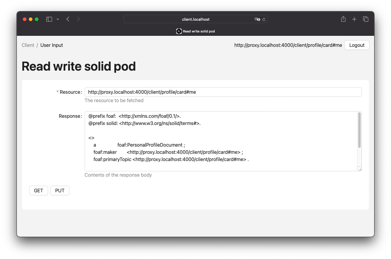
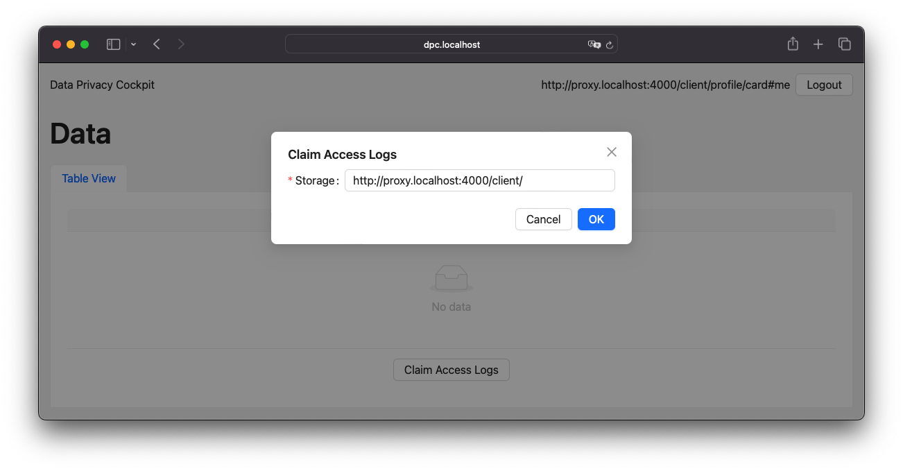
The process of claiming access logs is relatively straightforward, requiring only a single form input in the UI. When an agent is logged in, the related storage can be detected automatically. If not, the input field allows custom URL input. Upon submission, the rest of the process occurs in the background. Figure 11 presents a screenshot of this UI.
Log Discovery
The logs in the DPC API server are represented as routes. These routes will either return an empty turtle file or attempt to resolve the claim and receive the actual files from the claimed storages. Figure 12 provides an illustration of this process.

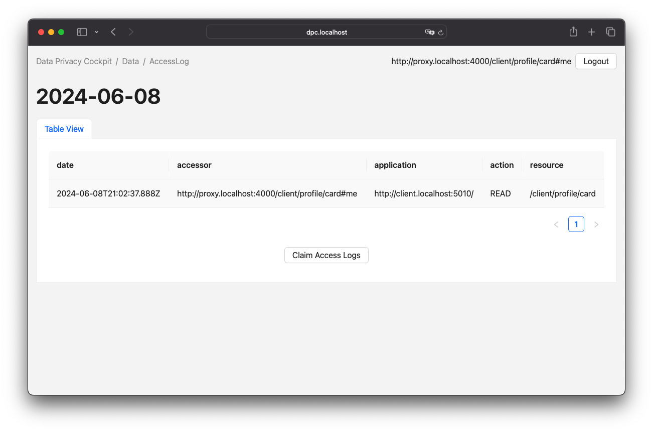
Upon successful claiming of an access log container, the agent is presented with a view of the logged entries. This view is represented by a table, as illustrated in Figure 13.
6.3.2. Process References
Authorization Client Credentials Flow
The authorization client credentials flow, is a authorization technique defined in RFC 6749, Section 4.4[30].
To obtain the authorization token, send a POST request to the authorization server with the client ID and secret in the authentication header.
It is also necessary to set the grant type to client_credentials and the scope to webid.
The proxy will forward requests as every CRUD request because the authorization server is not directly accessible.
Figure 14 provides an illustration of this process.

Authorization Code Flow
Another authorization technique is the authorization code flow, as defined in RFC 6749, Section 4.1[31]. It is important to note that this technique differs from a Authorization Client Credentials Flow, especially in the way that redirects are part of this flow. This means that user inputs are required in this technique and they cannot run automated.
Forwarded Request
Request forwarding is quite simple, the proxy receives a CRUD request that is passed through the server. The returning server response will take the path back to the original requester. Since the requester can be the proxy itself, there needs to be some kind of guard to prevent infinite recursive calls. If the requester is someone other than the proxy, the Data Privacy Cockpit middleware can be executed. In certain cases, it may be necessary to read and evaluate the server response, which can be done during a response interception[32] step. In this process, a pair of client ID and the name of the registered web application, which were submitted during the OIDC process, is stored. This information can be utilized in authorized requests by processing the authorization token and retrieving the client ID from the store to obtain the corresponding application name. Figure 15 provides an illustration of this process.

DPC Middleware
The Data Privacy Cockpit is a Solid application that requires a dedicated agent and client credentials. The agent must log in before any other actions can be executed. If successful, the container resources of the requested resource will be searched until the corresponding storage is found or no more container resources are left to search. If a storage is found, access logs will be created or updated. Figure 16 provides an illustration of this process.

Lookup Claim Data in Registry
The process of retrieving claimed data follows the data discovery outlined in the Solid Application Interoperability specification. If the data does not already exist, it will be created. Finally, the registry data will be filtered from the set of data and returned. Figure 17 provides an illustration of this process.

Create Dynamic Namespace
A process will be initiated to create the Access Log Vocabulary and related ShapeTree and ShEx resources on the server in a dynamic manner during runtime. This process will occur within the individual storage resource of the module agent. Furthermore, the ACL resources will be added with access privileges set to public accessibility.
Create or Update Dataset
The update of a dataset begins with a test to determine if the resource already exists on the server. If it does, it will be received as a dataset. Otherwise, a new dataset will be created. The dataset will be enriched with new data and stored on the server. Figure 18 provides an illustration of this process.

Initialize a Verification Code
To initialize a verification code, start by generating a random key. The DPC API will store the verification code, storage, WebID, and additional data in a location accessible to the DPC agent for later verification. If the DPC API cannot access the client’s storage, the process will terminate without adding data to the DPC storage. Figure 19 provides an illustration of this process.

Write Verification Code to Client Storage
Writing the verification code consists of two steps. The first step is to write the verification code to the client’s storage. Since the code must be read by the DPC agent, the second step is to grant read permissions for the agent. Figure 20 provides an illustration of this process.

Write Verification Code to DPC Storage
Before writing the verification code to the DPC storage, the agent must first verify their identity. After authorization, a new claim containing the verification code and associated storage will be added to the list of claims, along with the storage-related claims in the registry. Figure 21 provides an illustration of this process.

Get Claimed Resource
The process of obtaining a claimed resource will be managed by the DPC agent. The WebID from the active client session will be used to retrieve the claims from the registry, along with the storage and verification code for that claim. The DPC agent will then retrieve the verification code from the storage. If both verification codes match, the request will be forwarded by the DPC agent. Figure 22 provides an illustration of this process.

7. Technology
7.1. Technology Stack
The technological stack is entirely based on ECMAScript respectively TypeScript. Server-side scripts will be executed in the Node.js runtime environment, while client-side scripts will utilise the corresponding engine of the browser.
7.1.1. Project Structure
The project was created as a multi-package repository, with pnpm [33] serving as the package manager for Node.js-based projects.
A multi-package repository is a repository that is used to group a variety of packages and artifacts that are maintained in a single repository.
The initial two levels of the project directory, including the packages contained within this project repository, are illustrated in Figure 23.
Metadata directories and files are excluded from this diagram.
Node child packages are stored in the ./apps directory, the ./packages directory, and the ./tests/benchmark directory.
These directories contain the source code for the experimental prototype.
The ./docs directory contains all documents related to the research.
The ./scripts directory contains custom build scripts that are used to produce the project’s artifacts.
The ./tests/http directory contains simple HTTP test files, which are used for singular tests.

The Node.js packages contained in the ./packages folder are generic source code fragments utilized in the ./apps packages.
The ./packages/core folder contains the most basic data, which is used in nearly every package.
In contrast, the ./packages/ui folder contains data relevant to the user interface or general view logic.
These packages are required by the ./apps/client and ./apps/dpc packages, as they represent applications that an actual user can interact with.
The ./apps/client package can be used to test client requests, while the ./apps/dpc package is used to view the monitoring data captured by the DPC middleware.
The middleware, however, is part of the ./apps/proxy package, which delegates the ./apps/server package, a wrapper package for the CSS, to the Node.js process.
The ./tests/benchmark package is a wrapper package for Apache JMeter, which is called from the Node.js process.
7.1.2. Third-Party Software
A variety of packages are utilised in the experimental prototype, with two packages of particular significance for this study: the Community Solid Server[34] and Inrupt JavaScript Client Libraries[35].
The Community Solider Server is a modular implementation of the Solid Protocol, which allows for a variety of configuration options due to its modularity. With the exception of the configurations that must be changed for the Experiments, the default configurations have been applied, as generated by the Community Solider Server configuration generator[36]. The configuration options that have a particular influence on the tested scenario are data management and account management options. The data storage component of data management is configured as the file system by default, which may have an impact on performance due to the necessity of writing files to the hard drive. Similarly, locks are stored in the file system and are used to prevent simultaneous write operations on the same resource. The default authorization mechanism is WAC. With regard to account management, it is important to note that suffixes are used as storage container URLs, rather than subdomains. Furthermore, account management includes the identity provider, which uses OIDC. The complete configuration file can be accessed in Appendix B.
At the client side, the Inrupt JavaScript Client Library is used to access RDF resources in a uniformed way. Consequently, it is almost impossible to use CSS vendor APIs.
The network protocol HTTP is employed for all operations in this research. Security measures such as HTTPS are not considered in this analysis. Similarly, the Solid Provider has not been tested in an isolated network with a proxy, which must be the only public-accessible instance for a secure run in production environments. This potential issue has been tested with Docker[37], but it did not affect the research scenario.
7.2. Limits of the Technology Stack
The technology stack has some impact on what is possible within the Solid Protocol. The limitations mentioned here refer to the essential parts of the stack as listed in the Technology Stack.
As mentioned earlier, CSS has a locking mechanism. Locks are used to prevent concurrent writes to the same resource. According to the configuration generator documentation, disabling this mechanism can cause data corruption. Changing this mechanism to in-memory locking is not sufficient when multiple worker threads are used. Although multiple worker threads are not tested in this analysis, the file system configuration is used to ensure that variations of the tested scenario are allowed in later work. Consequently, concurrent writing to a resource is prohibited by the CSS.
The Inrupt JavaScript Client Libraries offer only limited support for appending RDF triples to an existing resource.
The guide on modifying an existing dataset[38] illustrates that it is advisable to load a resource, modify it, and then save it.
This approach results in the execution of a READ and (RE)CREATE requests, instead of a single UPDATE request.
The attempt to append data will result in an HTTP 412 Precondition Failed error response, as explained in Inrupt’s save considerations.
These considerations are particularly relevant in the context of System Design, where they influence the system’s behavior, such as the creation or update of a dataset.
7.3. Deviation from Specification
The divergence from the specifications, whether in the form of Solid Protocol or Solid Application Interoperability, is of vital importance in the analysis of the proposed DPC approach. Any variation or unspecified use of an API may result in inconsistent or corrupt behaviour with other Solid Providers, which is detrimental to the generic approach that the proposed apprach is intended to be. During the Design and Implementation of this approach, two main discrepancies in the specifications were identified.
The initial issue was identified as being related to the actual implementation of the utilized technologies.
It would be reasonable to consider this in the specification, as it is a generalized concern.
Both the proxy and server components engage in periodic self-requests for the purpose of writing access logs and verifying the identity.
Given the absence of a mechanism to prevent or limit recursive network calls, it has been necessary to implement a variety of custom mechanisms to exclude these requests from monitoring.
In the case of the Forwarded Request, this is presented as an isLoggableRequest condition.
The application logic behind this condition is comprised of three distinct tests.
One such test is that of a request header, which may or may not include a hash value.
This value is applied to requests originating from the same web instance.
Should the hash value in question align with the expected value, the request in question will not be monitored.
Another filter for self-requests is the test to determine if the request URL matches the OIDC configuration path.
This path is typically /.well-known/openid-configuration.
In the case of CSS, this could be enhanced to include all internal data, as all internal URL paths begin with /., but this technique is limited to CSS and is not a standard pattern.
Finally, all agent WebIDs, which are utilized in middleware, are to be disregarded.
As the connection is established within the middleware, the agents to be filtered are known at the time they are to be excluded.
The filters for the OIDC configuration path, as well as the WebID of the middleware agent, are obtained from the server instance.
In the absence of control over the fetcher, as is the case here, the request header hash mechanism cannot be employed.
Another issue that was identified was the necessity of writing data to container resources.
With a fundamental understanding of the CRUD operations, it would be relatively straightforward to perform a POST/PUT or PATCH request to the resource in question, for example: PUT http://proxy.localhost:4000/client/data/.
However, this is not the case with CSS, as writing to container resources involves writing metadata.
Metadata refers to the Description Resources mechanism, where a resource is linked as illustrated in Listing 2.
With the used version of CSS, only PATCH methods are permitted, resulting in a request such as PATCH http://proxy.localhost:4000/client/data/.meta for the creation of data and GET http://proxy.localhost:4000/client/data/ if the data is read.
This behavior is exclusive to CSS, yet a fundamental API to employ when Solid Application Interoperability is implemented, as the ShapeTrees are read from the resources containers, thereby inheriting the shape to the child resources.
8. Related Work
Since 2018, the Solid Community Group[39] has been responsible for the management of the Solid Project. Due to the relatively small size of the group and its limited public visibility, the level of activity within the community is correspondingly low. Consequently, research sources are limited and related work is almost non-existent. However, some work and projects do consider related ideas.
A research project that has greatly inspired this thesis is the showcase project of a Solid-based government-to-citizen use case as described by Both et al. (2024). In this project, the data of a citizen is maintained by several Data Trustees, one for each governmental authority. In this model, the citizen passes references to the maintained data to the individual authority, ensuring that the data is only stored once at the responsible authority. This, however, resulted in the creation of a highly interconnected system, even with a relatively low number of authorities. The issue that emerged was that, following the citizen’s granting of access, the actual retrieval of data from the authority was not transparent to the citizen. In order to regain control over the exposed data, the concept of a DPC was introduced. With the problem of interconnected data in mind, as outlined in ISSUE-2.
In addition to the research topics, there have been projects in the public sector addressing the issue of data exchange, access control, and transparency. X-Roads[40] is an alternative ecosystem to Solid that offers unified and secure data exchange between organizations. It is maintained by the Nordic Institute for Interoperability Solutions[41]. One of its central services is a monitoring system that logs data, as pointed out by O’Donoghue et al. (2023). A project that is already utilizing Solid is Athumi[42], which acts as a trust partner for the purpose of strengthening data collaboration between consumers, businesses, and public agencies in Flanders. Diederich (2023) describes the conclusion of a prototype period for a data privacy cockpit in Germany. This cockpit was developed within an enclosed ecosystem to monitor a newly introduced digital registry, with the objective of achieving transparency for citizens and their data.
Esposito et al. (2023) did consider security concerns, as outlined in the GDPR and other pertinent documents, in order to demonstrate their relevance to the measures in the Solid Protocol. In this context, the lack of adequate logs has been criticized, as addressed in this work. They have been separated into two kinds of logs: "Event logs for system behaviour and user activities" and "Tamper-proof access logs with different views". As system behavior cannot be monitored from outside a system without modifying the Solid Provider, only access logs have been considered in the proposed approach. One aspect that has been deliberately excluded is the recommendation not to provide logs in external storage resources. This is due to the Esposito et al. (2023) study, which has identified this as an unnecessary risk for the transmission of privacy-critical data over the internet. This may be the case for transmissions over public networks, but in this approach, the proxy and the Solid Provider must be served in an enclosed network, as the proxy is the only server that might be publicly accessible. Slabbinck et al. (2024) did propose a method for limiting access to a resource for a defined period of time, with the aim of gaining control over the exposed data utilizing an automated agent. The automated agent mechanism was also employed in the work of Slabbinck et al. (2023), where the agent executes automated background processes to synchronize the state of a smart bulb with a Solid storage. The concept of acting on behalf of another individual was also explored in the work of Schmid et al. (2024), where access privileges can be delegated to another agent via a proxy[43].
One of the primary concerns of this thesis is to determine the impact of the proposed approach on Performance Efficiency. In this context, it is reasonable to align the proposed approach with known benchmarks to determine the incremental impact it will have. This will enable a clear understanding of the proposed approach’s potential impact. There are numerous benchmarks, such as the Proxy-Benchmarks[44], which are designed to assess the efficiency of proxies. In addition, Pan et al. (2018) presents a variety of RDF benchmark datasets, including the Lehigh University Benchmark (LUBM)[45], the Berlin SPARQL Benchmark (BSBM), the DBpedia SPARQL Benchmark, and the SP^2Bench. These benchmarks address specific scenarios, such as the passing through of a proxy or the querying of RDF data. The obstacle in using the proxy is that the efficiency of the proxy is not of interest; only the module that is executed within the proxy is relevant. Furthermore, querying RDF is not applicable to the context of this work, as it lives in a ROA, working with the actual resources. The only benchmark that could be found suitable for Solid-based scenarios is SolidBench.js[46], which is limited to requests without Authentication. As the objective of the DPC is to monitor authenticated requests, it is necessary to implement a bespoke mechanism, as outlined in the Network Parameters section of Chapter 9.
Part IV: Analysis
The analysis will integrate the theoretical framework and the implementation in order to generate reliable results regarding the system’s performance in various scenarios. The analysis is divided into two sections. The 9th chapter will exhibit the configuration of the Experiments, demonstrating how the tests were conducted. In the subsequent chapter on Validation, the results of the tests will be presented and analyzed, with techniques and measures introduced in the theoretical framework.
9. Experiments
9.1. Test Environment
Prior to initiating experimentation, it is imperative to specify the test environment. The server and proxy applications will be build and run the platform depicted in Listing 18.
$ system_profiler SPSoftwareDataType SPHardwareDataType

Software:

    System Software Overview:

      System Version: macOS 12.7.4 (21H1123)
      Kernel Version: Darwin 21.6.0
      Boot Volume: Macintosh HD
      ...

Hardware:

    Hardware Overview:

      Model Name: MacBook Pro
      Model Identifier: MacBookPro13,2
      Processor Name: Dual-Core Intel Core i7
      Processor Speed: 3,3 GHz
      Number of Processors: 1
      Total Number of Cores: 2
      L2 Cache (per Core): 256 KB
      L3 Cache: 4 MB
      Hyper-Threading Technology: Enabled
      Memory: 16 GB
      System Firmware Version: 526.0.0.0.0
      OS Loader Version: 540.120.3~37
      ...
The installed version of Node.js is that described in Listing 19.
$ node -v
v22.1.0
In order to run the tests, certain adjustments had to be made to the Solid Provider as part of the Technology Stack. It was necessary to extend the OIDC session (client credential expiration time) and lock lifetimes. It is necessary to extend the expiration time for the session, as the Authentication process has not been tested and will be established once and for all runnable test plans. The extend of lock lifetimes was needed, as the default lifetimes did not cover long-running operations, as those expected in the tests. The CSS configuration generator[47] recommends that in this case the lock lifetime value be increased. The default lifetime of a client credential token is 0.6 seconds, which has been increased to 172800 seconds (equivalent to two days). The lifetime of locks has been increased by the same amount.
9.2. Test Parameters
It is important to note that the tested use case only considers Authorised CRUD Requests, which are designated as Process Entries for users and any type of agent. Consequently, the Log Claiming and Log Discovery functionality has not been subjected to a direct examination, as its performance is dependent on the application logic implemented and not on the underlying concept. It is essential to subject the parameters of the network APIs and the aspects of the Solid Ecosystem, which are defined by a set of options provided by the test executer, to exhaustive testing. All of these test parameters are summarized in a test matrix at the end of this section.
9.2.1. Network Parameters
The scenarios to be tested on this system will cover CRUD operations on RDF resources, as these are the most common for ROAs and Solid applications, respectively.
As suggested in the System section, a CRUD sequence will be built based on the CRUD resource lifecycle state machine described there.
To generate a sequence that represents the behavior of an actual agent, a probability ![]() must be applied to all possible transitions
must be applied to all possible transitions ![]() :
:

Table 2 lists the assumptions for all possible transitions. It considers that the amount of read operations is significantly higher than other operations. Updates to and deletions of existing resources occur with greater frequency than the initial creation of a resource. Furthermore, the spreading of probability values occurs with the smallest probability when a resource is created.
i |
1 |
2 |
3 |
4 |
|
|---|---|---|---|---|---|
Transition |
Create |
Read |
Update |
Delete |
|
t |
1 |
10 |
2 |
15 |
|
P(t) |
0.06 |
0.66 |
0.13 |
1 |
|
The create transition can only be applied to deleted resources and to new resources.
When a create transition is determined, another probability process will delegate it equally to the deleted resources or create a new resource.
In order to ascertain which resource is affected by the CRUD operation, a subscript index is applied to the transition identifier.
For example, the following notation is used: C0 R1 U0 D0.
The uppercase letters represent the first character of the CRUD operations in any order, run sequentially.
The container resources are organized in a collection hierarchy, with the default depth set to 1.
In the context of the configurations of CSS, this equates to the storage resource, for example, http://proxy.localhost:4000/client/.
Deeper hierarchies, such as URLs that are based on the aforementioned example, are ignored in the tested scenarios.
9.2.2. Data Privacy Cockpit Parameters
The DPC has three states that are considered configuration parameters. One state is that of a claimed storage container, which monitors the corresponding resources in the storage. In contrast, the second state is that of a non-claimed storage container, which will not monitor any requests to the storage. However, this state still needs to determine if it is in the list of storage containers to be tracked. The third state is that of a configuration that bypasses the proxy module and skips the logging process of the middleware. This is necessary because there is no existing benchmark against which the DPC configuration can be compared. In order to ascertain the extent of the increase in network load, it is essential to measure the bypassed scenario, which will serve as a reference value against which the other DPC configurations can be compared.
The bypass scenario utilizes the bypass mechanism of Forwarded Requests, which is used for internal self requests. The mechanism in adds a randomized header hash to the request, which is read during the request process in order to disable the DPC on self-calling. This is demonstrated in Listing 20.
GET http://proxy.localhost:4000/client/profile/card#me
X-Proxy-Bypass-Token: af8649fb
A new environment variable has been introduced for testing purposes, which allows the automatic generation of the hash value to be static value to be used instead. This is demonstrated in Listing 21.
PROXY_BYPASS_TOKEN="af8649fb"9.2.3. Solid Ecosystem Parameters
The Solid Protocol and Solid Application Interoperability permit two primary components to scale continuously within a running and growing Solid Provider.
These components are the amount of storages managed by the Solid Provider and the registered ShapeTrees.
For the purpose of mass testing, the client storage resources will have an additional amount.
The amount will be applied to client storages (e.g., client42), resulting in a client storage resource such as http://proxy.localhost:4000/client42/.
In the context of a test case where this client has a claimed storage resource, all client storages between client1 and the given index are considered claimed as well.
The index also determines the storage container in which the CRUD operations will be executed.
This is necessary to validate the edge cases with a large amount of storages.
The same logic will apply to the ShapeTrees.
Consequently, it is necessary to register a greater amount of ShapeTrees before the actual required ShapeTree appears in the register.
9.2.4. Apache JMeter Parameters
In order to perform the tests, version 5.6.3 of Apache JMeter[48] was utilized. According to Nevedrov (2006), JMeter has three relevant test parameters that are contained by a thread group: the number of threads, the ramp-up time, and the loop count.
| Number of Threads |
The number of threads, represents the number of user, using a web service. |
| Ramp-up Period |
The time needed for the creation of the threads is defined by the the ramp-up period. (The start time for a thread is calculated as the ramp-up period divided by the number of threads, multiplied by the thread index[49].) |
| Loop Count |
The number of times a thread group executes each of its elements. |
In addition to the thread group, there are samplers, which are configurable requests to the server, such as HTTP requests.
Each of these HTTP samplers represents a transition in the CRUD sequence.
Specifically, Ci is mapped to a PUT, Ri to a GET, Ui to a PUT, and Di to a DELETE method in the request.
The POST API, as an alternative to Ci, was not considered in the tested scenarios.
In order to enforce a sequential run, independent of the execution time, thread group and loop, these values are applied to the resource name, as shown in Listing 22.
http://proxy.localhost:4000/client/run1716802767389_thread3_loop1_resource09.2.5. Test Parameters Matrix
This section presents a comprehensive list of selected test parameters, organized by context. The aggregation of each parameter into a test plan is summarized in Table 7 at the end of this section.
Each execution of a test plan involves a preparation phase, which precedes the actual execution of the test plan. A general preparation step is to seed all client storage containers into the Solid Provider before executing the test plan. Similarly, DPC registries, claim data containers, and ShapeTrees are preproduced. Prior to each test run, the registry corresponding to the test case will be patched in the DPC social agent. The authorization will also occur outside of the actual execution of the test plan.
Table 3 presents the selection of Network Parameters utilized in the test plans, as detailed in Table 7. The ID column serves as a unique identifier for this parameter set. The CRUD sequence column indicates the CRUD operations that are executed during the test run. The run mode determines the order in which the operations are executed, either sequentially or in parallel. The hierarchical depth column indicates the depth of the resource container in which the operations are executed.
ID |
CRUD Sequence |
Run Mode |
Hierarchical Depth |
|---|---|---|---|
PARAM-CRUD-0 |
C0 |
sequential |
1 |
PARAM-CRUD-1 |
C0 R0 U0 R0 R0 R0 R0 R0 D0 C1 U1 R1 |
Table 4 presents the selection of Data Privacy Cockpit Parameters utilized in the test plans, as detailed in Table 7. The ID column serves as a unique identifier for this parameter. The description column provides an overview of the configuration applied to the module prior to the execution of the test run.
ID |
Description |
|---|---|
PARAM-DPC-N |
Non-Claimed Storage |
PARAM-DPC-C |
Claimed Storage |
PARAM-DPC-B |
Bypassed Proxy Module |
Table 5 presents the selection of Solid Ecosystem Parameters utilized in the test plans, as detailed in Table 7. The ID column serves as a unique identifier for this parameter set. The Storage Amount column refers to the amount and current index of storages used in the Solid Provider. Likewise, the ShapeTree Amount column defines the amount and index of ShapeTrees which are operated with. It should be noted that the selection of Data Privacy Cockpit Parameters may have an effect on this parameter. If the proxy module is bypassed, the Solid Ecosystem Parameters may become obsolete, as the DPC storage resource is not used. However, it is possible that this may have an influence on the performance of the Solid Provider.
ID |
Storage Amount |
ShapeTree Amount |
|---|---|---|
PARAM-SOLID-1-1 |
1 |
1 |
PARAM-SOLID-1-10 |
10 |
|
PARAM-SOLID-1-30 |
30 |
|
PARAM-SOLID-10-1 |
10 |
1 |
PARAM-SOLID-10-10 |
10 |
|
PARAM-SOLID-10-30 |
30 |
|
PARAM-SOLID-30-1 |
30 |
1 |
PARAM-SOLID-30-10 |
10 |
|
PARAM-SOLID-30-30 |
30 |
Table 6 presents the selection of Apache JMeter Parameters utilized in the test plans, as detailed in Table 7. The ID column serves as a unique identifier for this parameter set. The number of threads column specifies the number of users engaged in the web service. The ramp-up period has been fixed at 10 seconds. This value is a rounded estimate derived from the initial transition of the CRUD sequence, which is C0, and takes approximately 8 seconds. The initial transition will create the dynamic resources once, after which the system will be considered to be in a steady state. Given the results of previous testing, the loop count has been set to 10, which is a relatively small number of test runs for simple tests with one thread only. Nevertheless, this results in a considerable increase in the duration of the tests when the number of threads is augmented.
ID |
Number of Threads |
Ramp-up Period (in seconds) |
Loop Count |
|---|---|---|---|
PARAM-JMETER-1 |
1 |
10s |
10 |
PARAM-JMETER-2 |
2 |
||
PARAM-JMETER-3 |
3 |
||
PARAM-JMETER-4 |
4 |
||
PARAM-JMETER-5 |
5 |
||
PARAM-JMETER-6 |
6 |
||
PARAM-JMETER-7 |
7 |
||
PARAM-JMETER-8 |
8 |
||
PARAM-JMETER-10 |
10 |
||
PARAM-JMETER-30 |
30 |
Table 7 presents the aggregation of configurable options to be tested as test plans.
The schema column serves as a generic identifier for all parameterized test plans.
The experiment column denotes the experiment in which a test plan was executed.
The value of that cell is an incrementing natural number, starting at 1.
The Network Parameters column refers to the ID column of Table 3.
The Data Privacy Cockpit Parameters column refers to the ID column of Table 4.
The Solid Ecosystem Parameters column refers to the ID column of Table 5.
The Apache JMeter Parameters column refers to the ID column of Table 6.
Schema |
Experiment |
Network Parameters |
Data Privacy Cockpit Parameters |
Solid Ecosystem Parameters |
Apache JMeter Parameters |
|---|---|---|---|---|---|
PRE1. |
|
PARAM-CRUD-0 |
PARAM-DPC-C |
PARAM-SOLID-1-1 |
|
TP1. |
|
PARAM-CRUD-1 |
PARAM-DPC- |
PARAM-SOLID- |
PARAM-JMETER- |
10. Validation
This chapter serves to validate the Design and Implementation of the proposed system, thereby ensuring that it meets the quality standards set for both design and performance efficiency. The Quality Model should reveal any shortcomings inherent to this approach.
10.1. Design Quality Analysis
The design quality model is divided into two parts, which are to be analyzed in detail. The first part concerns the general Component Cohesion and recommendations for Component Coupling.
10.1.1. RRP Analysis
The RRP that proposes that the granularity of reuse is identical to that of release is not applicable to the system design and subsystem arrangement.
From the perspective of the project, each module can be reused at any time, either as it is contained by a shared package or can be moved there.
This is because the project is arranged as a multi-package repository, as described in the Project Structure.
From the perspective of HTTP APIs, this is not a problem, as the logic behind the request handlers is delegated to packages within the multi-package repository.
However, currently, the shared packages relevant for central aspects of the system are only separated into core and ui.
The core package contains global functions that are needed in all types of packages and applications, while the ui contains the parts that are used in graphical user interfaces and generic view logic.
Nevertheless, the core package could be divided into multiple packages, as not all of its functions are necessary in all dependent packages.
This would prevent the unnecessary release of packages if they were released separately.
10.1.2. CPP Analysis
According to the CCP, each component must change for the same reasons and at the same time. However, this is not feasible with the system design. For example, if the RDF vocabulary changes, every subsystem of the proposed system is affected, including the Solid Provider, the DPC middleware, and the DPC application. The Solid Provider must update the already persisted data structure if it is changed to an incompatible vocabulary. The DPC middleware produces new data in the form of the changed vocabulary, and the DPC application must be able to interpret and display the new data format if it requires custom view logic. Considering the related requirements of the Single Responsibility Principle, which states that each component should provide a service to a single actor, this appears to be a feasible solution. This is a satisfactory concern for both the DPC application and the middleware, since actors are defined as a group of one or more users. In this case, all Solid Provider users are grouped as an actor. The DPC application serves only as a user interface for handling access logs. The middleware is a proxy module that monitors traffic to the web server and creates the necessary resources if all conditions are met. However, complex scenarios where a single proxy module is responsible for multiple changes would violate the above rule.
10.1.3. CRP Analysis
The CRP demands that the components of a system should not impose unnecessary dependencies on others. The scenario is analogous to the one described in the RRP Analysis. From a Project Structure perspective, there are potential areas for improvement, but there are no violations on a conceptual level. However, when considering the HTTP APIs, there are relevant differences. With regard to component orchestration, it is possible to utilise the concept illustrated in Figure 4 in place of that in Figure 5. This would result in a reduction in the required storage containers, with the system becoming dependent on the client storage container alone. If the drawback to the system design is tolerable, the dependency on the module storage container could be regarded as an unnecessary dependency.
10.1.4. ADP Analysis
The ADP requires that no cyclical dependencies should be part of the system’s design. However, this is a component coupling principle that is not satisfied with the proposed approach. When a Forwarded Request is used, referred from the proxy as an actor, the proxy will request itself, meaning it has a dependency on itself and thereby a cyclic dependency. Even when a proxy is not requesting itself and requests are forwarded using forwarded headers, as illustrated in Listing 23, the server would still have a cyclic dependency. This is because the CSS requires the proxy hostname to be the base URL. Consequently, when Solid Provider verifies an agent from its own instance, it will still request itself through the proxy, which is then cyclic again.
GET http://server.localhost:3000/client/profile/card#me
X-Forwarded-Host: proxy.localhost:4000
X-Forwarded-Proto: http
10.1.5. TDD Analysis
The TDD proposes that the structural composition of a system cannot be predetermined at its inception. Instead, it is expected that this structure will naturally evolve as the system itself progresses. This is, in fact, an inherent aspect of proposed system development. It appears to be resolvable within the modular framework of a proxy, as illustrated in Figure 5 and Figure 4. Indeed, new proxy modules, such as the middleware component of the DPC, are added as additional middlewares, all of which are processed one after another.
10.1.6. SDP Analysis
Each variant of the Component Orchestration fulfills the need SDP, which requires that every component relies on a stable component. Given that the change of data does not affect the change frequency, the Solid Provider subsystem has the lowest change frequency. Given the conceptual purpose of the proposed system, all changes, including those made to the Solid Protocol, are handled in the proxy subsystem. Consequently, the changes are delegated to the proxy, which results in the higher change frequency being outsourced to it. Consequently, as the proxy is dependent on the server, the stable dependency requirement is satisfied. Any potential users of the public endpoint, such as the DPC application or any other HTTP client, are reliant on the stable proxy-server construct. As they are not responsible for any relevant application logic, they are free to modify their functionality as often as necessary.
10.1.7. SAP Analysis
The SAP is a principle that aims to separate high-level policies from the other functionalities of a system. If RDF, as a basis of Solid Ecosystem, is taken seriously, this is an inherent concept of it and thereby a satisfiable quality criterion without any additional design considerations. This is the case, as the full information structure and thereby the application logic is encapsulated in RDF data, although the processing needs to be implemented. The Solid Application Interoperability specification unifies a significant portion of this functionality.
10.2. Performance Efficiency Analysis
Due to a series of errors that occurred during the execution of the performance efficiency analysis tests, the tests were divided into several experiments. In order to obtain reliable results, each experiment was executed with different test parameters and outcomes. Prior to executing the individual experiments, a pretest was conducted to gain insights into how a single request effectively influences the system.
10.2.1. Pretest
The pretest is a single Authorised CRUD Request, which creates a resource on the webserver as this will always be the first request of a Resource CRUD Lifecycle . It will demonstrate how a request will effectively influence the overall system, particularly in terms of the multiplication of requests.
A behavior that comes with the vendor-agnostic approach of the DPC Middleware when the Data Privacy Cockpit Parameter is set to C.
The Solid Ecosystem Parameters are set to 1.
The corresponding request to the pretest is presented in Listing 24.
PUT http://proxy.localhost:4000/client/resource.ttl
Authorization: Bearer eyJhbGciOiJFUzI1NiIsInR5cCI6ImF0K2p3dCIsImtpZCI6...
Content-Type: text/turtle
Accept-Encoding: br, deflate, gzip, x-gzip
Accept: */*

<ex:s> <ex:p> <ex:o>.
The first run of the pretest is PRE1.1 as shown in Table 7. It uses the request shown in Listing 24. The corresponding console output when the request is executed is shown in Listing 25. As can be seen in the output, the proxy receives a total of 30 requests, all of which are triggered by the DPC Middleware or the Solid Provider.
GET /.well-known/openid-configuration 200 869.917 ms - 1628
POST /.oidc/token 200 355.897 ms - 689
GET /dpc/profile/card 200 41.793 ms - 455
GET /.well-known/openid-configuration 200 5.183 ms - 1628
GET /.well-known/openid-configuration 200 11.725 ms - 1628
GET /.oidc/jwks 200 28.389 ms - 215
HEAD /client/ 200 1308.392 ms - -
GET /dpc/profile/card 200 328.853 ms - 455
GET /dpc/profile/card 200 357.867 ms - 455
GET /dpc/registries 200 423.300 ms - 748
GET /dpc/ns/log 200 445.733 ms - 879
GET /dpc/ns/log.shex 200 194.348 ms - 489
GET /dpc/ns/log.tree 200 34.588 ms - 331
GET /dpc/data/2acf59fe.../AccessLog/ 200 1104.491 ms - 4920
GET /dpc/data/2acf59fe.../AccessLog/2024-06-15 404 193.933 ms - 106
PUT /dpc/data/2acf59fe.../AccessLog/2024-06-15 201 478.769 ms - -
HEAD /client/ 200 1218.440 ms - -
GET /dpc/profile/card 200 259.182 ms - 455
GET /dpc/profile/card 200 444.497 ms - 455
GET /dpc/registries 200 441.340 ms - 748
GET /dpc/ns/log 200 451.397 ms - 879
GET /dpc/ns/log.shex 200 498.059 ms - 489
GET /dpc/ns/log.tree 200 51.325 ms - 331
GET /dpc/data/2acf59fe.../AccessLog/ 200 1066.895 ms - 5140
GET /dpc/data/2acf59fe.../AccessLog/2024-06-15 200 497.765 ms - 444
PATCH /dpc/data/2acf59fe.../AccessLog/2024-06-15 205 1205.967 ms - -
GET /.well-known/openid-configuration 200 10.385 ms - 1628
GET /client/profile/card 200 6839.827 ms - 451
GET /.well-known/openid-configuration 200 14.058 ms - 1628
PUT /client/resource.ttl 201 14371.603 ms - -
Follow-up requests (PRE1.2) have significantly fewer total requests. A total of 12, as presented in Listing 26. It is less because the DPC agent running in the DPC Middleware has already established a session, which only needs to be done once. The same applies to the Authorization of the requesting agent, which in both cases is the owner of the storage resource.
HEAD /client/ 200 144.839 ms - -
GET /dpc/profile/card 200 128.599 ms - 455
GET /dpc/profile/card 200 300.807 ms - 455
GET /dpc/registries 200 525.531 ms - 748
GET /dpc/ns/log 200 61.741 ms - 879
GET /dpc/ns/log.shex 200 492.467 ms - 489
GET /dpc/ns/log.tree 200 52.425 ms - 331
GET /dpc/data/2acf59fe.../AccessLog/ 200 702.389 ms - 5140
GET /dpc/data/2acf59fe.../AccessLog/2024-06-15 200 435.568 ms - 542
PATCH /dpc/data/2acf59fe.../AccessLog/2024-06-15 205 97.043 ms - -
GET /.well-known/openid-configuration 200 8.759 ms - 1628
PUT /client/resource.ttl 205 4004.135 ms - -
10.2.2. Experiment 1
The initial experiment was designed to provide an overview of a greater number of tests, with parameters that were not intended to create a critical load on the system. The objective was to identify potential areas of heavy load and to produce detailed insight based on these initial results.
| Parameters |
All test plans were executed with the variable |
| Total Reports |
81 |
| Reports |
TP1.1-B-1-1-1, TP1.1-B-1-1-10, TP1.1-B-1-1-30, TP1.1-B-1-10-1, TP1.1-B-1-10-10, TP1.1-B-1-10-30, TP1.1-B-1-30-1, TP1.1-B-1-30-10, TP1.1-B-1-30-30, TP1.1-B-10-1-1, TP1.1-B-10-1-10, TP1.1-B-10-1-30, TP1.1-B-10-10-1, TP1.1-B-10-10-10, TP1.1-B-10-10-30, TP1.1-B-10-30-1, TP1.1-B-10-30-10, TP1.1-B-10-30-30, TP1.1-B-30-1-1, TP1.1-B-30-1-10, TP1.1-B-30-1-30, TP1.1-B-30-10-1, TP1.1-B-30-10-10, TP1.1-B-30-10-30, TP1.1-B-30-30-1, TP1.1-B-30-30-10, TP1.1-B-30-30-30, TP1.1-N-1-1-1, TP1.1-N-1-1-10, TP1.1-N-1-1-30, TP1.1-N-1-10-1, TP1.1-N-1-10-10, TP1.1-N-1-10-30, TP1.1-N-1-30-1, TP1.1-N-1-30-10, TP1.1-N-1-30-30, TP1.1-N-10-1-1, TP1.1-N-10-1-10, TP1.1-N-10-1-30, TP1.1-N-10-10-1, TP1.1-N-10-10-10, TP1.1-N-10-10-30, TP1.1-N-10-30-1, TP1.1-N-10-30-10, TP1.1-N-10-30-30, TP1.1-N-30-1-1, TP1.1-N-30-1-10, TP1.1-N-30-1-30, TP1.1-N-30-10-1, TP1.1-N-30-10-10, TP1.1-N-30-10-30, TP1.1-N-30-30-1, TP1.1-N-30-30-10, TP1.1-N-30-30-30, TP1.1-C-1-1-1, TP1.1-C-1-1-10, TP1.1-C-1-1-30, TP1.1-C-1-10-1, TP1.1-C-1-10-10, TP1.1-C-1-10-30, TP1.1-C-1-30-1, TP1.1-C-1-30-10, TP1.1-C-1-30-30, TP1.1-C-10-1-1, TP1.1-C-10-1-10, TP1.1-C-10-1-30, TP1.1-C-10-10-1, TP1.1-C-10-10-10, TP1.1-C-10-10-30, TP1.1-C-10-30-1, TP1.1-C-10-30-10, TP1.1-C-10-30-30, TP1.1-C-30-1-1, TP1.1-C-30-1-10, TP1.1-C-30-1-30[50], TP1.1-C-30-10-1, TP1.1-C-30-10-10, TP1.1-C-30-10-30, TP1.1-C-30-30-1, TP1.1-C-30-30-10, and TP1.1-C-30-30-30[51] |
| Outcome |
The tests were conducted over a period of approximately seven days, including the occurrence of errors in the proposed system.
On restarting the applications of the system, the tests could be continued from that point onwards.
Upon analysis of the state of the application, it was found that the |
Further analysis of the performance efficiency has been omitted due to the invalidity of the test reports that were created. Despite the completion of the experiment, all tests have been flagged as invalid due to the inability to determine the exact time of occurrence of errors in the proposed system.
10.2.3. Experiment 2
The second experiment was planed with the same intend as the initial experiment, with a smaller scope, that only tackles the edge cases and brings less reports to analyse. The primary concern however was to get valid results and to overcome the error that has been found in the first experiment.
| Parameters |
All test plans were executed with the variable |
| Total Reports |
24 |
| Reports |
TP1.2-B-1-1-1, TP1.2-B-1-1-30, TP1.2-B-1-30-1, TP1.2-B-1-30-30, TP1.2-B-30-1-1, TP1.2-B-30-1-30, TP1.2-B-30-30-1, TP1.2-B-30-30-30, TP1.2-N-1-1-1, TP1.2-N-1-1-30, TP1.2-N-1-30-1, TP1.2-N-1-30-30, TP1.2-N-30-1-1, TP1.2-N-30-1-30, TP1.2-N-30-30-1, TP1.2-N-30-30-30, TP1.2-C-1-1-1, TP1.2-C-1-1-30, TP1.2-C-1-30-1, TP1.2-C-1-30-30, TP1.2-C-30-1-1, TP1.2-C-30-1-30, TP1.2-C-30-30-1, and TP1.2-C-30-30-30 |
| Outcome |
The tests were conducted over a period of approximately three days, including the occurrence of application errors. It appeared that the application was failing again, resulting in invalid results. The reason for this failure was the same as the error that occurred in Experiment 1. |
Further analysis of the performance efficiency has been omitted due to the invalidity of the test reports that were created. Despite the completion of the experiment, all tests have been flagged as invalid due to the inability to determine the exact time of occurrence of errors in the proposed system.
10.2.4. Experiment 3
The erroneous behavior observed in Experiment 1 was not accidental, as verified in Experiment 2. Consequently, the third experiment was conducted under the assumption that an error would occur at some point, resulting in the loss of relevant data. To further investigate this error, individual tests were run to examine the specific edge cases that led to these critical errors.
| Parameters |
All test plans were executed with the variable |
| Total Reports |
7 |
| Reports |
TP1.3-1-1-30, TP1.3-1-1-10, TP1.3-30-30-10, TP1.3-30-10-10, TP1.3-10-10-10, TP1.3-10-1-10, and TP1.3-1-10-10 |
| Outcome |
The only tests that completed without error were TP1.3-1-1-10. All other tests resulted in one of three erroneous situations. TP1.3-1-1-30, TP1.3-10-1-10, and TP1.3-1-10-10 exhibited critical system errors, resulting in immediate cessation of the application, as illustrated in Listing 27. The second error, as demonstrated in Listing 28, was thrown in TP1.3-30-30-10, TP1.3-30-10-10, and TP1.3-10-10-10. The error in question was a network error, which did not stop the application from functioning. The processing continued as normal. In each of the aforementioned test reports, the server returns an error message indicating that a header has already been sent. This error is occasionally observed, in the proxy console. |
A detailed analysis reveals three errors that occur internally while processing requests.
The most significant differences relate to the storage amount (p) and the amount of ShapeTrees (q).
However, a strict behavior could not be determined.
It appears that test plans executed with lower values for p and/or q than those used in other tests within this experiment result in an error message indicating that a file for the locking system of the Solid Provider is requested that does not exist.
This error resulted in the immediate termination of the process (exit code 1).
This is a unique function of the CSS as described in Third-Party Software.
The corresponding error message is shown in Listing 1.
Process is halting due to an uncaughtException with error ENOENT: no such file or directory, stat '/SEACT/apps/server/data/storage/.internal/locks/00169a735ca3f756b7e8d18151283856'
/SEACT/node_modules/.pnpm/@[email protected]/node_modules/@solid/community-server/dist/util/locking/FileSystemResourceLocker.js:152
            throw err;
            ^
@seact/server:start:
[Error: ENOENT: no such file or directory, stat '/SEACT/apps/server/data/storage/.internal/locks/00169a735ca3f756b7e8d18151283856'] {
  errno: -2,
  code: 'ECOMPROMISED',
  syscall: 'stat',
  path: '/SEACT/apps/server/data/storage/.internal/locks/00169a735ca3f756b7e8d18151283856'
}

Node.js v22.1.0
ELIFECYCLE Command failed with exit code 1.
Tests conducted with p and/or q values that were higher than those of other tests resulted in a fetch exception when attempting to locate storage resources.
This aligns with the results observed in Experiment 1 and 2.
An example of this error is shown in Listing 28.
The error did not result in the immediate termination of the process.
TypeError: fetch failed
    at node:internal/deps/undici/undici:12502:13
    at async findStorage (/SEACT/packages/core/dist/index.js:617:29)
    at async findDataRegistrationsInClaimContainer (/SEACT/packages/core/dist/index.js:726:19)
    at async createLog (/SEACT/apps/proxy/dist/index.js:303:47)
The third error, which occurred during the processing of the requests, was a "header has already been sent" error.
In such a case, the responseInterceptor, which is employed in the context of Forwarded Requests, attempts to modify the response object before returning it to the original requester.
The error did not result in the immediate termination of the process.
10.2.5. Experiment 4
This experiment aimed to tackle the locking issue found in Experiment 3. As previously stated in the Test Environment section, for testing purposes, the lifetime of locks has been increased to 172800 seconds, in order to be capable of handling long-running requests. In order to verify that this is not a miss configuration, the configuration has been reset to its default for this experiment.
| Parameters |
The test plan was executed with the variable |
| Total Reports |
1 |
| Reports |
TP1.4-10-10-10 |
| Outcome |
The test terminated almost instantaneously, thus confirming the necessity for longer lock lifetimes. |
10.2.6. Experiment 5
The initial test scenarios were designed with considerably elevated numeric test parameters.
Upon consideration of the assumptions presented in Experiment 3, it becomes evident that a solution to the deletion of the .meta resource, as outlined in Experiment 1, is necessary.
The most trivial solution for that is to create the required files with a user with more privileges.
As the files are persisted as files, these files are replaced by the same files created with a sudo user.
This effectively prohibits the application, which is executed with current user privileges only, from deleting the resource.
| Parameters |
The test plan was executed with the variable |
| Total Reports |
1 |
| Reports |
TP1.5-10-10-10 |
| Outcome |
The test plan could not be executed, due to a critical internal server error, as shown in Listing 29. |
The error message displayed in Listing 29 indicates that the Solid Provider lacks the necessary permissions to access the relevant resources. The intention was to prevent the deletion of this resource. However, the actual result was that the server process lacked sufficient privileges for read-only purposes.
{
  "name": "InternalServerError",
  "message": "Received unexpected non-HttpError: EACCES: permission denied, open '/SEACT/apps/server/data/storage/client10/.meta'",
  "statusCode": 500,
  "errorCode": "H500",
  "details": {}
}
10.2.7. Experiment 6
As an alternative to Experiment 4 and Experiment 5, the objective of this experiment was to address the third issue identified in Experiment 3.
This was achieved by deactivating the selfHandleResponse and responseInterceptor properties in the proxy.
By doing so, all post-processing of requests from the proxy to the server was handled by the proxy library.
This should prevent any manipulation of the response object, as the response has already been sent.
| Parameters |
The test plan was executed with the variable |
| Total Reports |
1 |
| Reports |
TP1.6-10-10-10 |
| Outcome |
The tests were conducted for approximately four hours before being terminated.
The process ended with the error message |
10.2.8. Experiment 7
The straightforward solutions proposed in Experiments 4, 5, and 6 did not result in any improvement in the errors identified in Experiment 3. Consequently, patches[53] to the applications have been implemented in order to address the aforementioned errors. The errors that have been identified thus far suggest that the proxy module is unable to handle the volume of requests it receives without causing errors. In particular, the issue of writing to the same file appears to be problematic, potentially leading to the locking issue. The DPC Middleware is configured to write logs on a daily basis, which means that a single file will be written in every request. This modification was implemented in this experiment with the intention of ensuring that a new log is written per request. Furthermore, the Create Dynamic Namespace process has been replaced with static paths, as this could also be handled in a bootstrapping step, which might lead to unnecessary requests. At last, the version of the Node.js Test Environment has been reduced to 20.14.0, the current LTS version. This was done as it is the preferred version of the oidc-provider[54], a CSS inherent module[55].
| Parameters |
The test plan was executed with the variable |
| Total Reports |
3 |
| Reports |
TP1.7-10-1-1, TP1.7-10-10-1, and TP1.7-10-10-10 |
| Outcome |
While the tests TP1.7-10-1-1 and TP1.7-10-10-1 were successfully completed, TP1.7-10-10-10 was unsuccessful. This leads to the conclusion that the greatest impact is derived from the number of threads executed in parallel. |
10.2.9. Experiment 8
In Experiment 8, the limitations of the r value, which represents the number of threads, are examined based on the assumptions of Experiment 7.
These assumptions posit that concurrency represents a significant challenge for the proposed approach.
The value was incremented until the first error occurred, with the step width set to 1, starting at 1. This process was repeated until an erroneous test run was observed.
In order to extend the runtime, the loop count, as part of the Apache JMeter Parameters, has been set to 1.
Furthermore, the modifications to the application introduced in Experiment 7 have also been applied in this experiment.
| Parameters |
The test plan was executed with the variable |
| Total Reports |
8 |
| Reports |
TP1.8-C-10-10-1, TP1.8-C-10-10-2, TP1.8-C-10-10-3, TP1.8-C-10-10-4, TP1.8-C-10-10-5, TP1.8-C-10-10-6, TP1.8-C-10-10-7, and TP1.8-C-10-10-8 |
| Outcome |
The first test run that was prematurely terminated was the test with an |
10.2.10. Experiment 9
The objective of this experiment was to determine whether the observed behavior in Experiment 8 would also manifest with a loop count of 10.
In this experiment, the number of threads was limited to 7.
Furthermore, the modifications to the application introduced in Experiment 7 have also been applied in this experiment.
| Parameters |
The test plan was executed with the variable |
| Total Reports |
3 |
| Reports |
TP1.9-C-10-10-1, TP1.9-C-10-10-2, and TP1.9-C-10-10-3 |
| Outcome |
The first failure occurred with |
10.2.11. Experiment 10
The 10th and final experiment was intended to run in a larger context, to receive comparable results within the limits discovered in previous experiments. Furthermore, the modifications to the application introduced in Experiment 7 have also been applied in this experiment.
| Parameters |
All test plans were executed with the variable |
| Total Reports |
24 |
| Reports |
TP1.10-B-1-1-1, TP1.10-B-1-1-2, TP1.10-B-1-10-1, TP1.10-B-1-10-2, TP1.10-B-10-1-1, TP1.10-B-10-1-2, TP1.10-B-10-10-1[56], TP1.10-B-10-10-2[57], TP1.10-N-1-1-1, TP1.10-N-1-1-2, TP1.10-N-1-10-1, TP1.10-N-1-10-2, TP1.10-N-10-1-1, TP1.10-N-10-1-2, TP1.10-N-10-10-1, TP1.10-N-10-10-2, TP1.10-C-1-1-1, TP1.10-C-1-1-2, TP1.10-C-1-10-1, TP1.10-C-1-10-2, TP1.10-C-10-1-1, TP1.10-C-10-1-2, TP1.10-C-10-10-1[58], and TP1.10-C-10-10-2[59] |
| Outcome |
Tests with a |
Table 8, Table 9, and Table 10 summarize of the test runs for TP1.10-i-10-10-r, with i in {B, C} and r in {1, 2}.
They provide an overview of how the system behaves at different loads and configurations.
The first column of the tables refers to the test plan that was carried out, followed by the i value of this test.
The next column contains the corresponding p, q, and r values.
Table headers that appear below these variables indicate the configuration of these variables.
The Test Run Error Summary is presented in Table 8.
Its shows the percent of failed requests, returning a network status code[60] greater or equals 400.
Other requests are considered successful, in a network status code range 100-399.
It can be observed that the complexity of the test run is directly proportional to the number of failed requests, even with a limited number of results.
When the Data Privacy Cockpit Parameters are set to C, the failed requests are on average 2.92% higher than when the proxy module is bypassed B.
Furthermore, the erroneous requests also increase when the number of threads (r) is increased.
It is noteworthy that the number of errors also increases in bypassed cases, despite the original request not triggering any subprocesses.
TP1.10 |
|
|
|---|---|---|
|
B |
C |
10-10-1 |
0.00 % |
2.50 % |
10-10-2 |
0.83 % |
4.17 % |
Table 9 presents the averaged response time in seconds, rounded to two decimals. The standard deviation of B is 0,31681 s, the standard deviation of C is 5,560185 s.
The values presented are consistent with the results presented in Table 8.
A higher complexity results in a higher average reaction time.
The values of the B column are still below 1 second, which is the maximum limit that can cause a delay in the user’s cognitive process.
The C column, on the other hand, dramatically increases the amount of time a potential user can focus on a process.
Based on the observations of Nielsen (1993), the value is limited to 10 seconds, which is exceeded by about 4 times even with the lowest possible r value of 1. With this value set to 2, it is exceeded by about 5 times the recommended limit.
TP1.10 |
|
|
|---|---|---|
|
B |
C |
10-10-1 |
0.04 s |
41.21 s |
10-10-2 |
0.67 s |
52.33 s |
The overall performance of the proposed system is quantified by the throughput measurements presented in Table 10. The values listed are in transactions per second. The standard deviation of B is 12,87 Transactions/s, the standard deviation of C is 0,005 Transactions/s.
As observed in the measurements shown in Table 8 and Table 9, the throughput drops significantly when the complexity of the system and the amount of threads increases. The average decline in transactions per second is 13.29. In considering the aspects identified by IBM as influencing throughput, namely processing overhead in the software, the degree of parallelism supported by the software, and the types of transactions processed, it appears that these factors may be plausible causes of the issues that have been found.
TP1.10 |
|
|
|---|---|---|
|
B |
C |
10-10-1 |
26.41 Transactions/s |
0.01 Transactions/s |
10-10-2 |
0.20 Transactions/s |
0.02 Transactions/s |
Part V: Reflection
This part serves to reflect upon the subject of the aforementioned work. The analysis of decisions is conducted in a critical manner, and alternative options are presented. In the Discussion, the effects of these decisions are identified and, if necessary, justified. In the chapter on Future Work, a number of alternative approaches are presented that represent an interesting continuation of the topic under discussion. Finally, a Conclusion with a comprehensive reflection on the research and the resulting knowledge gained is provided.
11. Discussion
This section of the study is devoted to a critical analysis and comparison of the present work with related works. Since there are few such works, the focus is on critical reflection.
The System Design encompasses a multitude of elements that have a significant impact on the processing of data, particularly in terms of Performance Efficiency. It is important to note that the individual aspects are not distinct decisions that are made in isolation. Each of the individual options encourages or enforces a Logical Topology, with either the Client as Data Owner or a Trustee as Data Owner. Finally, it is crucial to identify the approach that aligns most closely with the system’s requirements, even if it involves trade-offs. This will ensure that the system design achieves the desired quality, tailored to the specific needs of the system. In this context, the Trustee as Data Owner, with an Opt-In as Data Capturing Strategy was chosen, as this approach appeared to offer the most promising results. However, subsequent analysis has revealed that this decision may not be the optimal choice in terms of system reliability. As evidenced by the findings of the Performance Efficiency Analysis, the logging of access can be easily disabled while still serving data.
The most significant impact has been observed in the area of Solid Application Interoperability, as the application model is based on it.
In this work, this protocol extension has only been implemented to a limited extent, as it is a protocol that should be implemented by the Solid Provider itself.
A complete implementation of this protocol in a custom proxy module would require a significant amount of time that is beyond the scope of this work.
Therefore, a partial implementation was deemed appropriate as it could be integrated seamlessly into the existing Solid Ecosystem landscape.
Additionally, alternative variations of Solid Application Interoperability were considered for the System Design.
Some of these variations could potentially make the Claim Vocabulary obsolete, as they could be implemented through a mechanism inherent to Solid Application Interoperability.
If this is indeed a viable option, a dedicated experiment should be conducted to assess its feasibility.
The specifications appear to have been designed for a single-tent context.
Nevertheless, all the tested variations resulted in a situation where the accessing agent must declare its participation in the specification, as illustrated in the Personal Profile Document (Data Model).
In the proposed approach, however, only the DPC agent is required to declare an interop:Agent in the Personal Profile Document (Data Model).
As this agent is under the control of the hosting party, no external agents are required to declare anything.
Consequently, they may continue to utilise the Solid Protocol, which they are already familiar with.
One disadvantage of the use of the Solid Application Interoperability was the Deviation from the Specification in terms of container resource creation.
The specification recommends that the Shape Trees (Data Model) be located in the container resource response.
In the case of the DPC, this refers to the access log shape trees.
However, patching the data associated with a container resource is a vendor-specific process.
In CSS, providing data to a container resource necessitates operations on the linked Description Resource, a rather unconventional mechanism.
The use of vendor-specific APIs prevents the implementation of a generalistic approach that was attempted.
Another crucial decision was to utilise self-invocation for Forwarded Requests from the proxy to the Solid Provider.
Instead, the requests could have been forwarded directly to the server, as illustrated in Listing 23.
This approach would have avoided proxying the requests, while simultaneously enabling the middleware to initiate new requests to the server and process the messages before returning them to the original requester.
This serialization step would be a necessity, as the Solid Provider would return references to a server that is not publicly accessible within its headers and the body.
This pattern was rejected, as it is very difficult to maintain, as every request format must be processible and adjusted on an individual format level.
When using the self-invoking technique with the proxy set as baseUrl [61] within the Solid Provider, the correct references are used immediately.
The disadvantage of this approach is that internal requests must be filtered and excluded to prevent recursive requests.
There are several options for doing so, including the use of a randomized token to bypass the proxy, as shown in Listing 20, as well as the exclusion of selected paths from logging.
However, this approach violates design paradigms, particularly the prevention of cyclic dependencies, as discussed in the ADP Analysis.
The apparent trade-off between control and flexibility proved to be illusory in the context of the prototype.
Whenever a request was initiated, whether by the proxy or the server, there was a significant risk that the filtering mechanism would fail to exclude it, resulting in an infinite loop of recursive calls.
Although this could be stabilized for the purposes of this test, updates to the Solid Provider are particularly risky, especially if they involve protocol changes that might necessitate the submission of new requests that are not part of the filtering mechanism.
A generic approach, such as overwriting the fetcher globally, in the context of the proxy and the server, might be a viable solution that could limit these risks.
Authentication is a primary concern, particularly in the context of sensitive data such as access logs.
In Data Capturing Strategies, an opt-in option has been introduced, which has been used for the System Design.
Although the mechanism of consent aligns with the ideas of the Solid Ecosystem, it may have an impact on the data security that has not been considered in this work.
The method of Ownership Verification, as proposed, necessitates the writing of a resource for verification, as presented in Write Verification Code to Client Storage.
One potential risk is that, when an agent is logging in to any web application, the application acts on behalf of the agent.
Consequently, this means that the application has complete access rights to the storage resource, and thereby to the verification resource, which is part of the storage.
In the event that the application is malicious, it may gain access to the logged data.
Another potential attack scenario, which is specific to CSS, is to simply temporarily or permanently delete the .meta resource at the storage resource level.
This description resource marks a container as a storage resource by adding http://www.w3.org/ns/pim/space#Storage as the link header.
Upon the removal of the resource, the lookup in the DPC Middleware will not be disrupted, thus allowing for unlogged access.
The root of both attack scenarios lies in the sharing of privileges to web applications, which is a general problem of the Solid Protocol.
However, for the purpose of access logging, an opt-in approach may not be as suitable as the Data Capturing Strategy, due to the allowed absence of observed resource paths.
A more suitable approach might be to consider a permanent approach, as every path will be observed at any time.
One aspect of data storage that is contingent upon the Logical Topology selected is the Data Storage Structure. The arrangement of the data that is tracked must be organized when stored in the client storage. When the data is stored at the site of the Data Trustee, it is crucial that the data be grouped in a way that only authorized agents are able to access it. This is a challenging issue, as the creation of a storage resource per agent seems a convenient solution. However, this isolated data space is not part of a defined workflow in the Solid Protocol. The creation of container resources does have a unified API, although CSS does this in a non-compliant way.
The introduction of a Custom Vocabulary for this work is also open to debate. While it is legitimate to introduce a custom vocabulary, RDF-based systems benefit the most if the vocabulary is a common or at least publicly known vocabulary. The application of one of the aforementioned vocabularies, namely the ODRL Information Model[62] or the DPV[63], would effect the System Design, potentially leading to increased fetches and, consequently, an impact on Performance Efficiency. In considering this, it is recommended that the proposed approach for system design involves the adaptation to an established vocabulary, with the aim of ensuring compatibility and reducing the potential for issues. Another significant consideration is that the access log employs a vocabulary that has already been established, such as the HTTP Vocabulary[64]. This process can be implemented within the individual application. By doing so, it is possible to utilize an established vocabulary while maintaining human readability, at least at the presentation layer.
As previously mentioned, Authentication is one of the primary solutions provided by the Solid Ecosystem. It is important to note that the Client Credential Flow, which has been used to login the DPC agent, is not part of the Solid-OIDC specification, as defined by Coburn et al. (2022). Instead, a Authorization Code Flow (Basic Flow) is provided, which does require interaction by the login party. This presents a challenge for automated agents. While the majority of Solid Providers do support the Authorization Client Credentials Flow, this is not guaranteed, and therefore represents an unacceptably high level of risk when establishing a general approach.
As previously stated in Chapter 8, this system is significantly influenced by Both et al. (2024). The circumstances there are entirely distinct, as multiple disparate agents are attempting to access one’s data. The present analysis is limited to the case of an individual attempting to access their own data. This may not be of particular interest to a potential DPC user, without the information of which application has accessed the data. This is why the detection for the application name has been introduced, as previously discussed in the section on Forwarded Requests. In this process, the DPC Middleware was required to observe the OIDC login procedure and obtain the name of the application. In this scenario, tokens are stored in the runtime memory, which may be susceptible to data loss. The effect of this mechanism is also unclear, particularly in the context of a session that has expired and a fresh token is requested. In addition to the technical limitations, this approach is constrained to the Authorization Code Flow, which may restrict the available functions of the Solid Provider or the reliability of this approach is uncertain.
The most obvious shortcoming of the proposed approach is the lack of a stable and reliable use.
Even if this approach is not implemented in its most optimal manner, the impact on the system’s performance is significant, as evidenced by the Performance Efficiency Analysis.
Despite the implementation of ten experiments, 20 of the 24 test runs remained unanalyzable due to errors or invalid results.
All previous considerations are obsolete in the event that the stability cannot be brought to a reasonable level.
Following the examination of the tested scenario, there remain numerous potential causes for the observed instability.
In Experiment 10, the observed increase in average response times was 0.63 seconds, as shown in column B of Table 9.
This appears to be a notable phenomenon, particularly given that the threads are only incremented by one.
It is noteworthy that the DPC logic is bypassed in this scenario, which leads to the assumption that the erroneous behavior may be caused by another system component.
In this scenario, the source of the problem may be the proxy, the server, or even the client itself.
This does not explain the observed increase of almost 1000-fold when enabling the DPC, as shown in column C.
However, it may explain a greater portion of the increment, as the DPC will multiply each request, as well as the potential error.
Consequently, the accumulated response time of the DPC is increased, with the root cause being one of the other system components.
The results of the experiments yielded only limited insights into the research questions. The test results from Experiment 10 were the only results that could effectively be used to answer the questions. These results were reduced to bypassed and claimed storage cases due to the errors that occurred. Additionally, the storage and ShapeTree amount were only tested with a number of 10. The number of threads could only be tested up to two. Given the limited data resulting from the parameters, it is challenging to provide an accurate assessment of the system load and influencing parameters as required in QUEST-2 and QUEST-3. The questions that can be answered by the data are summarized in Chapter 13.
12. Future Work
In the context of further work on this project, it is important to consider a number of additional factors that could potentially enhance the System Design and the Performance Efficiency.
As previously discussed, the most crucial objective is to identify a method for stabilizing and optimizing this approach. Otherwise, any attempt to enhance this technique will inevitably lead to performance or load issues. It would be beneficial to initiate future work with this issue in mind, beginning with a test of the Solid Provider and continuing with a proxy and all other participating system components. This will enable an evaluation of the performance of each component, such as CSS, in relation to the approach in question. Ultimately, a test of the specific configuration must be conducted in order to achieve optimal efficiency. This may include the number of workers[65] for multithreaded mode. An alternative would be to consider a different server, such as the Manas solid server[66], which focuses on robustness and concurrency.
It is assumed that the access logs are only accessible to the owner of a storage resource. However, in a default configuration of CSS, this information is unknown when receiving an arbitrary resource from a storage resource. This particular Solid Provider does provide a visibility option[67] to assign a Identity to a storage resource. If activated, the reference is contained as a link header in the response, as demonstrated in Listing 30. This may potentially make the entire claiming mechanism obsolete, which would be an interesting topic for further investigation.
link: <http://example-tld/client/profile/card#me>; rel="http://www.w3.org/ns/solid/terms#owner"In this work, the issue of application-level caching has not been a concern. The objective has been to ensure that all resources and relevant information are always the latest version, with no older version delivered from any caching mechanism. However, in real-world scenarios, this approach would be considered a bad practice, as it would result in unnecessary network penetration. The proposed approach does offer some instances in which caching may be suitable. For instance, caching can be employed to discover the containing storage resource. In this case, an arbitrary resource is reduced to the closest storage resource container. This process occurs each time a resource is requested, even if there is minimal change frequency. This is a scenario that should be investigated further to determine if caching is applicable. There may be other scenarios that emerge as a result of further research on this topic.
Should the proposed System Design be retained, with a file located in the client’s storage resource being read from the DPC agent, new possibilities emerge.
Clients may restrict or manipulate access from their individual storage resources without modifying the code.
Currently, this resource contains only the claim:Verification Thing.
However, it could also contain filtering rules for requests, which, for instance, limit access by specific patterns.
A research program in this direction could lead to a significant increase in control over data privacy, based on the transparency benefits achieved here.
A final suggestion for future work is to apply the proposed approach to other proxy modules. The DPC Middleware is an illustrative example of how limits in the Solid Ecosystem or the individual Solid Provider could be overcome with the use of a intermediary design pattern, such as a proxy. However, it is important to note that the DPC Middleware is only a single module with a specific purpose. It would be of significant interest to ascertain the consequences of multiple proxy modules with distinct purposes. The implications of a more extensive implementation of this concept, as exemplified by the DPC Middleware, may be of interest, as it represents a generic idea.
13. Conclusion
This thesis builds upon the prototypical implementation of the Data Privacy Cockpit (DPC) to explore the general possibility of extending Access Control and Traceability. The DPC was designed for data-driven web-based systems with a vendor-agnostic approach over a web interface, with Solid as a technical foundation. The ability to view actual requests to private resources on the web server represents a novel task within the Solid Ecosystem. For the first time, it is possible to ascertain which agents have been granted access to specific resources. However, these capabilities come with a drawback that has been extensively investigated. On the one hand, the impact on the System Design has been considered, and on the other hand, the loss of Performance Efficiency has been evaluated.
The analysis of the System Design Quality revealed that no critical violations of common design principles could be identified. The majority of the violations identified relate to the orchestration of system components and are part of the Component Cohesion principles. The only Component Coupling principle that was found to be violated is the ADP, which prohibits cyclic dependencies. As previously noted in the ADP Analysis, this is, like the Component Cohesion principles, a violation that is not by design. In this context, these principles have been discarded due to their maintenance benefits.
The findings of the Performance Efficiency Analysis are cause for concern. The proposed approach resulted in a notable decline in Performance Efficiency, as evidenced by an increase in average response time and throughput. However, the most significant drawback is the rise in error rate. This, in turn, has the potential to either result in the complete failure of the system or to cause it to skip the logging process. Even if executed correctly, the error rate, average response time, and throughput will increase significantly, effectively rendering the system inaccessible to users. The quantity of parallel threads describing the interaction of a single user is the most evident aspect influencing this.
When planning the Objectives and Research Interests of this thesis, it became evident that this examination could not encompass all aspects of the proposed approach. However, it was intended to identify the vulnerable aspects of this concept in order to determine whether this approach should be pursued in principle. When only considering the Analysis conducted, this approach appears to have no future. However, as previously discussed in Chapter 11, the erroneous behavior may not be solely attributed to this approach, as the other system components cannot be definitively excluded as a cause. While there have been other concerns discussed, such as potential security risks related to the Authentication and claiming mechanism, this approach remains a promising one due to its flexibility and various implementation options, as outlined in Component Orchestration. For the time being, no general recommendation or objection can be made. However, a caveat regarding the potential for high loads should be noted.
In addition to the general considerations, a specific question was posed in the context of this experiment. In order to provide a satisfactory answer, the sub-questions must first be addressed.
In QUEST-1, questions were raised about the fulfillment of the general Requirements for the system. The Functional Requirements, namely REQ-F1 and REQ-F2, were identified as being capable of being satisfied properly. A DPC client was identified as being responsible for the presentation of the access logs, in the event that the user in question has been granted sufficient privileges to claim a storage resource. This fulfills the requirement set out in REQ-F1. It was also possible, as requested in REQ-F2, to capture resource-related data, namely the date of the request, the requested resource and the action processed on the resource. Party-related data, such as the accessing identity, has also been accessible, although this depended on the access privileges of the individual resource. In the case of publicly accessible resources, no Identity is attached. However, an issue did emerge in this context. When a user accessed a resource from a Solid application with a private account, the user was the accessor. Therefore, the application field has been introduced to the access log. The data of this field are defined by the Solid application itself, and therefore cannot be relied upon without further effort. Parsing the metadata of a request, as demanded in REQ-NF1 of the Non-Functional Requirements, has been an implicit effort of REQ-F2. The actual Identity value is encoded in the token used in the Authentication process, which has been processed to slice out the Identity. The remaining Non-Functional Requirements have proven to be challenging to accomplish. REQ-NF2 requests compatibility with the Solid Protocol, which was achieved to a significant extent, although there was a Deviation from Specification. This primarily related to the web APIs exposed by CSS as Solid Provider. The most significant shortcoming is the one requested in REQ-NF3, namely the request for an appropriate time consumption. As demonstrated in the Performance Efficiency Analysis, the DPC requires up to five times the amount of time for a request to be processed when the logic is bypassed.
The findings from the analysis of REQ-NF3 align with the sub-question from QUEST-2. This question asks about the contribution to increasing the network requests and load. The proposed approach, as presented, will result in a multiplication of single requests triggered from the DPC Middleware. For initial requests, the network requests will result in a total number of 30 requests, with follow-ups resulting in 12. As previously stated, this will result in a significant increase in the average response time. Similarly, the throughput will decrease by an average of 13.29 transactions per second in the testable scenarios.
The Test Parameters that affect the system, as requested by QUEST-3, are difficult to name due to the number of errors within the Performance Efficiency Analysis. However, the number of parallel requests, referred to as the number of threads of the Apache JMeter Parameters, has a serious impact on system behavior. The number of threads represents the number of users using a service in parallel and has been limited to two users when a storage resource is claimed. The amount of storages, as well as the amount of ShapeTrees in the successfully tested scenario, was limited to 10. The loops in this test were also limited to 10, reducing them showed that up to 7 threads could be run. Both Apache JMeter Parameters affected the total number of requests made to the system, which is limited to a relatively small number if the DPC Middleware is to run without errors.
Finally, the answer to the key research question is that there was a System Design that could be used to increase transparency and access control. The answer of QUEST-1 proves that these goals, denoted as Functional Requirements, could be satisfied, even if the feasibility is questionable. However, the Non-Functional Requirements could not be fully satisfied. It is important to note that the compatibility with the Solid Protocol could not be fully implemented, and thus it is not fully vendor-agnostic. However, the most significant outcome of this experiment was the observed decline in performance. While the underlying cause of this decline could not be definitively determined, the frequency and severity of the observed performance drops, coupled with the high error rate, indicate that the proposed prototypical system is not a viable approach.
Appendix A: Full Logical Data Model

Appendix B: Community Solid Server Configuration
{
  "@context": "https://linkedsoftwaredependencies.org/bundles/npm/@solid/community-server/^7.0.0/components/context.jsonld",
  "import": [
    "css:config/app/init/default.json",
    "css:config/app/main/default.json",
    "css:config/app/variables/default.json",
    "css:config/http/handler/default.json",
    "css:config/http/middleware/default.json",
    "css:config/http/notifications/all.json",
    "css:config/http/server-factory/http.json",
    "css:config/http/static/default.json",
    "css:config/identity/access/public.json",
    "css:config/identity/email/default.json",
    "css:config/identity/handler/default.json",
    "css:config/identity/oidc/default.json",
    "css:config/identity/ownership/token.json",
    "css:config/identity/pod/static.json",
    "css:config/ldp/authentication/dpop-bearer.json",
    "css:config/ldp/authorization/webacl.json",
    "css:config/ldp/handler/default.json",
    "css:config/ldp/metadata-parser/default.json",
    "css:config/ldp/metadata-writer/default.json",
    "css:config/ldp/modes/default.json",
    "css:config/storage/backend/file.json",
    "css:config/storage/key-value/resource-store.json",
    "css:config/storage/location/pod.json",
    "css:config/storage/middleware/default.json",
    "css:config/util/auxiliary/acl.json",
    "css:config/util/identifiers/suffix.json",
    "css:config/util/index/default.json",
    "css:config/util/logging/winston.json",
    "css:config/util/representation-conversion/default.json",
    "css:config/util/resource-locker/file.json",
    "css:config/util/variables/default.json"
  ],
  "@graph": [
    {
      "comment": "The updated OIDC configuration.",
      "@type": "Override",
      "overrideInstance": {
        "@id": "urn:solid-server:default:IdentityProviderFactory"
      },
      "overrideParameters": {
        "@type": "IdentityProviderFactory",
        "config": {
          "claims": {
            "openid": [
              "azp"
            ],
            "webid": [
              "webid"
            ]
          },
          "clockTolerance": 120,
          "cookies": {
            "long": {
              "signed": true,
              "maxAge": 86400000
            },
            "short": {
              "signed": true
            }
          },
          "enabledJWA": {
            "dPoPSigningAlgValues": [
              "RS256",
              "RS384",
              "RS512",
              "PS256",
              "PS384",
              "PS512",
              "ES256",
              "ES256K",
              "ES384",
              "ES512",
              "EdDSA"
            ]
          },
          "features": {
            "claimsParameter": {
              "enabled": true
            },
            "clientCredentials": {
              "enabled": true
            },
            "devInteractions": {
              "enabled": false
            },
            "dPoP": {
              "enabled": true
            },
            "introspection": {
              "enabled": true
            },
            "registration": {
              "enabled": true
            },
            "revocation": {
              "enabled": true
            },
            "userinfo": {
              "enabled": false
            }
          },
          "scopes": [
            "openid",
            "profile",
            "offline_access",
            "webid"
          ],
          "subjectTypes": [
            "public"
          ],
          "ttl": {
            "AccessToken": 3600,
            "AuthorizationCode": 600,
            "BackchannelAuthenticationRequest": 600,
            "ClientCredentials": 172800000,
            "DeviceCode": 600,
            "Grant": 1209600,
            "IdToken": 3600,
            "Interaction": 3600,
            "RefreshToken": 86400,
            "Session": 1209600
          }
        }
      }
    },
    {
      "comment": "The new expiration time for inactive locks, in milliseconds.",
      "@type": "Override",
      "overrideInstance": {
        "@id": "urn:solid-server:default:ResourceLocker"
      },
      "overrideParameters": {
        "@type": "WrappedExpiringReadWriteLocker",
        "expiration": 172800000
      }
    }
  ]
}
Bibliography
Bergwinkl, T., Regalia, B., Felder, V., & Taelman, R. (2019). RDF/JS: Dataset specification 1.0. https://rdf.js.org/dataset-spec/
Bingham, J., Prud’hommeaux, E., & Pavlik, elf. (2023). Solid Application Interoperability. https://solid.github.io/data-interoperability-panel/specification/
Both, A., Gudat, F., Hoffmann, M., & Guzy, S. D. (2024). German Data-Sovereign Government-to-Citizen Use Case. https://solid.iis.fraunhofer.de/SCS-DS-IoT/public/2024/solid%20symposium/index.html
Capadisli, S. (2022). Web Access Control. https://solidproject.org/TR/wac
Coburn, A., Pavlik, elf, & Zagidulin, D. (2022). Solid-OIDC. https://solidproject.org/TR/oidc
Diederich, G. (2023). XDatenschutzcockpit Teil 1: Technologieunabhängige Spezifikation. https://www.xrepository.de/details/urn:xoev-de:kosit:standard:xdatenschutzcockpit
Esposito, C., Horne, R., Robaldo, L., Buelens, B., & Goesaert, E. (2023). Assessing the Solid Protocol in Relation to Security and Privacy Obligations. Information, 14(7), 411. https://doi.org/10.3390/info14070411
Fett, D., Campbell, B., Bradley, J., Lodderstedt, T., Jones, M. B., & Waite, D. (2023). OAuth 2.0 Demonstrating Proof of Possession (DPoP) (Request for Comments RFC 9449; Issue RFC 9449). Internet Engineering Task Force. https://doi.org/10.17487/RFC9449
Fielding, R., & Reschke, J. F. (2014). RFC7231. In IETF HTTP Working Group Specifications. https://httpwg.org/specs/rfc7231.html
Gamma, E. (Ed.). (2011). Design patterns: elements of reusable object-oriented software (39. printing). Addison-Wesley.
Luotonen, A., & Altis, K. (1994). World-Wide Web proxies. Computer Networks and ISDN Systems, 27(2), 147–154. https://doi.org/10.1016/0169-7552(94)90128-7
Martin, R. C. (2018). Clean architecture: das Praxis-Handbuch für professionelles Softwaredesign: Regeln und Paradigmen für effiziente Softwarestrukturen (M. Feilen & K. Lorenzen, Trans.; 1. Auflage). mitp.
Mozilla Developer Network. (2023). Protocol - MDN Web Docs Glossary. https://developer.mozilla.org/en-US/docs/Glossary/Protocol
Nottingham, M. (2017). RFC8288. In IETF HTTP Working Group Specifications. https://httpwg.org/specs/rfc8288.html
O’Donoghue, N., Kivimäki, P., Hautamäki, C., Seppälä, I., Reimets, E., & Reimets, E. (2023). X-Road Security Architecture. In X-Road Security Architecture \textbar X-Road. https://docs.x-road.global/Architecture/arc-sec_x_road_security_architecture.html#9-logging
Pan, Z., Zhu, T., Liu, H., & Ning, H. (2018). A survey of RDF management technologies and benchmark datasets. Journal of Ambient Intelligence and Humanized Computing, 9(5), 1693–1704. https://doi.org/10.1007/s12652-018-0876-2
Sambra, A., Story, H., & Berners-Lee, T. (2014). WebID 1.0. https://www.w3.org/2005/Incubator/webid/spec/identity/
Sarven, C., Berners-Lee, T., Verborgh, R., & Kjernsmo, K. (2022). Solid Protocol. https://solidproject.org/TR/protocol
Schmid, S., Schraudner, D., & Harth, A. (2024). The Rights Delegation Proxy: An Approach for Delegations in the Solid Dataspace. https://solid.iis.fraunhofer.de/SCS-DS-IoT/public/2024/solid%20symposium/index.html
Slabbinck, W., Dedecker, R., Rojas, J. A., & Verborgh, R. (2023). A Rule-Based Software Agent on Top of Personal Data Stores.
Colophon
Built with Asciidoctor 2.0.23, Asciidoctor Bibtex 0.9.0 and Asciidoctor Diagram 2.3.1 on linux-musl.