- Version
-
v1.0.1+10938074204, 2024-09-19
- Editor
-
Florian Gudat
- Module
-
Mastermodul (C533.2 Compulsory module)
https://modulux.htwk-leipzig.de/modulux/modul/6291 - Module Supervisor
-
Prof. Dr.-Ing. Jean-Alexander Müller
- Lecturer
-
Herr Prof. Dr. rer. nat. Andreas Both
Herr M. Sc. Michael Schmeißer - Institute
-
Leipzig University of Applied Sciences
- Faculty
-
Computer Science and Media
Acronyms
Namespaces
This enumeration lists the prefixes and the associated namespace. It will be used as the standard syntax for RDF prefixes. When a prefix is followed by a colon symbol, the part after the colon can be appended to the namespace URI, thereby creating a new URI.
| acl | |
| al |
dynamic (see [Custom Vocabulary]) |
| claim |
urn:claim# (see [Custom Vocabulary]) |
| ex |
example |
| foaf | |
| http | |
| interop | |
| ldp | |
| pim | |
| rdfs | |
| solid | |
| st |
The prefixes and namespaces enumerated above are applicable to diagrams, listings, and inline listings throughout the entirety of the document.
Notation
The diagrams in this document were generated using Asciidoctor Diagram 2.3.1[1] and its bundled PlantUML[2] version.
Unless otherwise specified, all framed diagrams will use the UML 2.5.1[3] standard, constrained by the limitations of PlantUML. As defined in the standard, the following abbreviations will be utilized to identify the type of UML diagram:
| cmp |
component diagram |
| sd |
interaction diagram |
| stm |
state machine diagram |
In addition to the UML abbreviation, the following abbreviations are used to identify non-UML diagrams:
| dm |
data model diagram; The information structure is entirely based on RDF, and will be presented as entity-relationship diagrams in Clive Finkelstein’s IE[4] notation, with some additional elements. The text in the double angle brackets will define the entity type (e.g., [Dataset], [Thing], …). The path labels indicate potential routes through the graph structure, while the number within the bracket indicates the branch that has been taken. |
| wbs |
work breakdown structure; This diagram is a decompositional diagram[5], intended for use in hierarchical structures, originally designed as a project management tool. In this context, it is used to illustrate any kind of hierarchical structure. |
All diagrams and figures presented in this work were created by the author. Any discrepancies have been highlighted in the corresponding figures.
1. Process Entries
There are three main behaviors that reflect interactions that can be executed directly or indirectly by the client: CRUD requests to a given resource, claiming log data, and discovering this data. The reference section defines subsequences that may be used in each of these interactions.
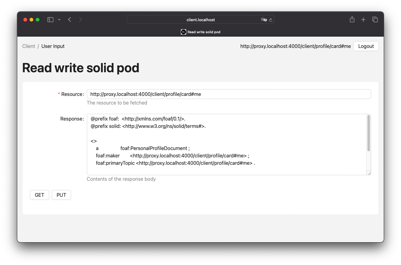
1.1. Authorised CRUD Requests
The process of authorizing a request can be divided into two steps. Firstly, an authorization token will be requested using an Authorization Client Credentials Flow or an alternative authorization process such as an Authorization Code Flow. Secondly, the CRUD request will be sent with an authorization header and the response will be provided accordingly. The key difference is that the request and response will be forwarded by the proxy instance. Figure 1 provides an illustration of this process.

1.2. Log Claiming
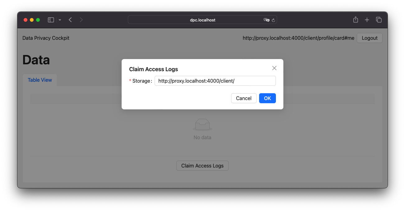
Network logs are captured by storage, not by WebID, and it is necessary to associate the data with a WebID at some point to make it readable to the owner. This is done by a claiming mechanism. This requires a Solid application that has access to both the user storage and the DPC storage. Both connections are handled by the DPC API server, and when the connections are established, the API initializes an verification code on behalf of the client agent to be verified by the DPC API server when it discovers the logs. Figure 3 provides an illustration of this process.

The process of claiming access logs is relatively straightforward, requiring only a single form input in the UI. When an agent is logged in, the related storage can be detected automatically. If not, the input field allows custom URL input. Upon submission, the rest of the process occurs in the background. Figure 4 presents a screenshot of this UI.
1.3. Log Discovery
The logs in the DPC API server are represented as routes. These routes will either return an empty turtle file or attempt to resolve the claim and receive the actual files from the claimed storages. Figure 5 provides an illustration of this process.

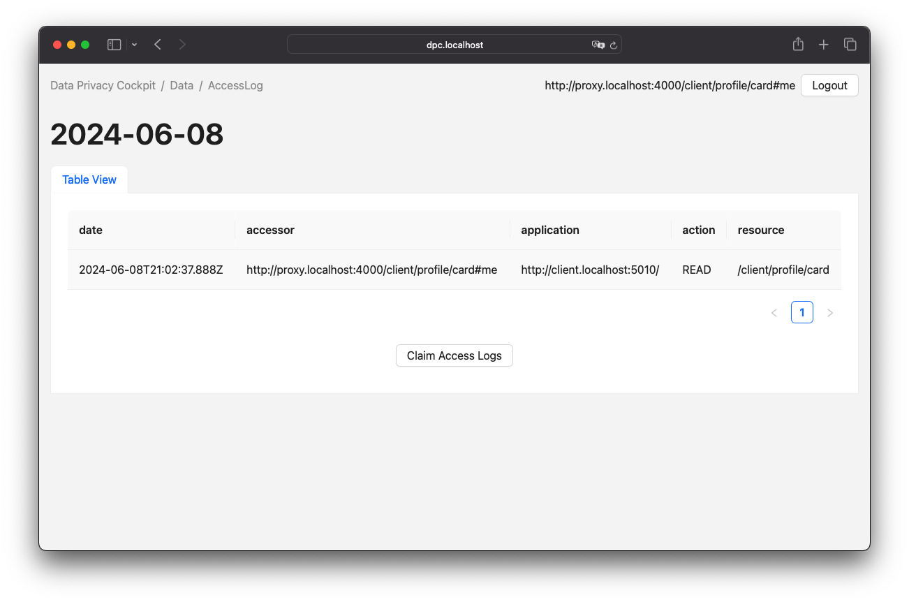
Upon successful claiming of an access log container, the agent is presented with a view of the logged entries. This view is represented by a table, as illustrated in Figure 6.
2. Process References
2.1. Authorization Client Credentials Flow
The authorization client credentials flow, is a authorization technique defined in RFC 6749, Section 4.4[6].
To obtain the authorization token, send a POST request to the authorization server with the client ID and secret in the authentication header.
It is also necessary to set the grant type to client_credentials and the scope to webid.
The proxy will forward requests as every CRUD request because the authorization server is not directly accessible.
Figure 7 provides an illustration of this process.

2.2. Authorization Code Flow
Another authorization technique is the authorization code flow, as defined in RFC 6749, Section 4.1[7]. It is important to note that this technique differs from a Authorization Client Credentials Flow, especially in the way that redirects are part of this flow. This means that user inputs are required in this technique and they cannot run automated.
2.3. Forwarded Request
Request forwarding is quite simple, the proxy receives a CRUD request that is passed through the server. The returning server response will take the path back to the original requester. Since the requester can be the proxy itself, there needs to be some kind of guard to prevent infinite recursive calls. If the requester is someone other than the proxy, the Data Privacy Cockpit middleware can be executed. In certain cases, it may be necessary to read and evaluate the server response, which can be done during a response interception[8] step. In this process, a pair of client ID and the name of the registered web application, which were submitted during the OIDC process, is stored. This information can be utilized in authorized requests by processing the authorization token and retrieving the client ID from the store to obtain the corresponding application name. Figure 8 provides an illustration of this process.

2.4. DPC Middleware
The Data Privacy Cockpit is a Solid application that requires a dedicated agent and client credentials. The agent must log in before any other actions can be executed. If successful, the container resources of the requested resource will be searched until the corresponding storage is found or no more container resources are left to search. If a storage is found, access logs will be created or updated. Figure 9 provides an illustration of this process.

2.5. Lookup Claim Data in Registry
The process of retrieving claimed data follows the data discovery outlined in the Solid Application Interoperability specification. If the data does not already exist, it will be created. Finally, the registry data will be filtered from the set of data and returned. Figure 10 provides an illustration of this process.

2.6. Create Dynamic Namespace
A process will be initiated to create the [Access Log Vocabulary] and related ShapeTree and ShEx resources on the server in a dynamic manner during runtime. This process will occur within the individual storage resource of the module agent. Furthermore, the ACL resources will be added with access privileges set to public accessibility.
2.7. Create or Update Dataset
The update of a dataset begins with a test to determine if the resource already exists on the server. If it does, it will be received as a dataset. Otherwise, a new dataset will be created. The dataset will be enriched with new data and stored on the server. Figure 11 provides an illustration of this process.

2.8. Initialize a Verification Code
To initialize a verification code, start by generating a random key. The DPC API will store the verification code, storage, WebID, and additional data in a location accessible to the DPC agent for later verification. If the DPC API cannot access the client’s storage, the process will terminate without adding data to the DPC storage. Figure 12 provides an illustration of this process.

2.9. Write Verification Code to Client Storage
Writing the verification code consists of two steps. The first step is to write the verification code to the client’s storage. Since the code must be read by the DPC agent, the second step is to grant read permissions for the agent. Figure 13 provides an illustration of this process.

2.10. Write Verification Code to DPC Storage
Before writing the verification code to the DPC storage, the agent must first verify their identity. After authorization, a new claim containing the verification code and associated storage will be added to the list of claims, along with the storage-related claims in the registry. Figure 14 provides an illustration of this process.

2.11. Get Claimed Resource
The process of obtaining a claimed resource will be managed by the DPC agent. The WebID from the active client session will be used to retrieve the claims from the registry, along with the storage and verification code for that claim. The DPC agent will then retrieve the verification code from the storage. If both verification codes match, the request will be forwarded by the DPC agent. Figure 15 provides an illustration of this process.

Bibliography
Colophon
Built with Asciidoctor 2.0.23, Asciidoctor Bibtex 0.9.0 and Asciidoctor Diagram 2.3.1 on linux-musl.